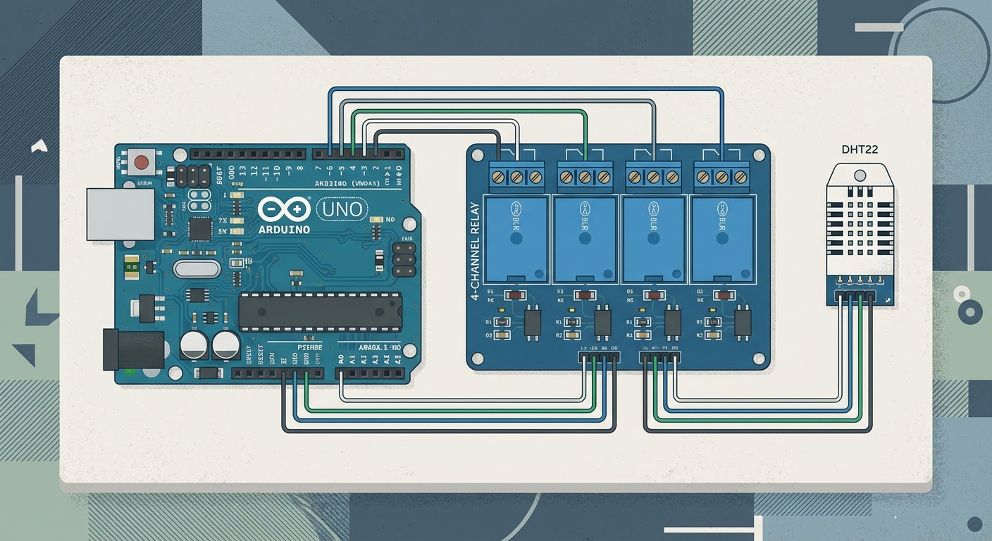
Keeping a terrarium at the perfect temperature and humidity is critical. Instead of manually turning heat lamps on and off, you can build a completely automated environmental controller. We’ll use an Arduino, a DHT22 sensor, and a terrifying 4-Channel Relay Module to switch high-voltage AC accessories on and off. If you wire this wrong, your pet lizard is going to have a very bad day.
What You’ll Learn
- How to read precise temperature and humidity data with the DHT22.
- How to safely trigger high-power 120V/240V AC accessories using relay modules.
- How to write “hysteresis” logic so your relays don’t constantly rapidly toggle on and off.
Parts Needed
- ELEGOO UNO R3 Board
- DHT22 Temperature & Humidity Sensor (More accurate than the DHT11)
- ELEGOO 4-Channel DC 5V Relay Module
- Jumper Wires & Breadboard
- Accessories: A standard heat lamp and a small terrarium humidifier/mister.
If you need a refresher on how relays work, check out Lesson 130: Power Up - Switching High Current with Relay Modules.
The Wiring
DHT22 Sensor:
- VCC -> 5V on Arduino
- GND -> GND on Arduino
- DAT (Data) -> Digital Pin 2 on Arduino
4-Channel Relay Module:
- VCC -> 5V on Arduino
- GND -> GND on Arduino
- IN1 (Relay 1 - Heater) -> Digital Pin 7
- IN2 (Relay 2 - Mister) -> Digital Pin 8
Note: For the AC side of the relays, you will need to cut the hot wire of an extension cord or power strip and run it through the Common (COM) and Normally Open (NO) terminals of the relay. WARNING: Working with mains voltage can be fatal. If you are a beginner, use an IoT relay power strip instead of cutting AC wires yourself.
The Code
Before uploading, make sure you have installed the DHT sensor library by Adafruit via the Arduino IDE Library Manager.
#include "DHT.h"

#define DHTPIN 2
#define DHTTYPE DHT22 // Using DHT22 sensor
DHT dht(DHTPIN, DHTTYPE);

// Relay Pins
const int heaterRelay = 7;
const int misterRelay = 8;

// Target Thresholds
const float targetTempF = 85.0; // Target Temperature in Fahrenheit
const float targetHumidity = 70.0; // Target Humidity %

// Hysteresis buffer to prevent rapid switching
const float tempBuffer = 2.0;
const float humidityBuffer = 5.0;

void setup() {
  Serial.begin(9600);
  dht.begin();

  pinMode(heaterRelay, OUTPUT);
  pinMode(misterRelay, OUTPUT);

  // Relays are often active-LOW. Start them turned OFF.
  digitalWrite(heaterRelay, HIGH);
  digitalWrite(misterRelay, HIGH);

  Serial.println("Terrarium Controller Initialized.");
}

void loop() {
  // Wait a few seconds between measurements.
  delay(2000);

  float h = dht.readHumidity();
  float t = dht.readTemperature(true); // true = Fahrenheit

  if (isnan(h) || isnan(t)) {
    Serial.println("Failed to read from DHT sensor!");
    return;
  }

  Serial.print("Humidity: ");
  Serial.print(h);
  Serial.print("%  Temperature: ");
  Serial.print(t);
  Serial.println("°F");

  // Temperature Logic (Heater)
  if (t < (targetTempF - tempBuffer)) {
    digitalWrite(heaterRelay, LOW); // Turn Heater ON
    Serial.println("Heater ON");
  } else if (t > targetTempF) {
    digitalWrite(heaterRelay, HIGH); // Turn Heater OFF
    Serial.println("Heater OFF");
  }

  // Humidity Logic (Mister)
  if (h < (targetHumidity - humidityBuffer)) {
    digitalWrite(misterRelay, LOW); // Turn Mister ON
    Serial.println("Mister ON");
  } else if (h > targetHumidity) {
    digitalWrite(misterRelay, HIGH); // Turn Mister OFF
    Serial.println("Mister OFF");
  }
}
Understanding Hysteresis
Notice the tempBuffer and humidityBuffer variables. If our target temperature is 85°F, and we just told the Arduino to turn the heater on below 85 and off above 85, the relay would click on and off constantly as the temperature hovered right at 84.9°F and 85.0°F.
By using a buffer (hysteresis), we tell the heater to only turn on if the temperature drops below 83°F (85 - 2), and stay on until it reaches exactly 85°F. This saves your relays and your equipment from burning out!
Taking It Further
Once you have the basics down, you can upgrade this project significantly:
- Add an I2C LCD Display to show the current temp and humidity on the outside of the tank.
- Upgrade to an ESP32 or ESP8266 to push the data to a cloud dashboard like we did in Project 27: IoT Weather Dashboard.
- Use an RTC (Real-Time Clock) module from Lesson 137 to turn on UV day lights during the day and red heat lamps at night.