Project 53: DIY ESP32 Audio Spectrum Visualizer (I2S & WS2812B)
We’ve all been there. You want to build a cool sound-reactive project. So you buy one of those cheap analog sound sensors (the ones with the little blue potentiometer), hook it up to your Arduino Uno, blast some AC/DC, and watch a single LED aggressively strobe like it’s having a seizure.
It doesn’t look like an audio visualizer. It looks like a distress signal.
The problem? Standard analog sound sensors are basically just clapping detectors. They can’t tell the difference between a bass drop and a dog barking. And the trusty Arduino Uno? It has the mathematical processing power of a potato. Trying to do real-time audio frequency analysis on an Uno is like trying to render 4K video on a calculator.
To build a real audio spectrum visualizer—the kind that separates the bass, the mids, and the highs into a glorious, flowing rainbow of light—we need more horsepower and a better ear.
Enter the ESP32 and the INMP441 I2S Microphone.
Today, we’re building a real-time, 256-LED Audio Spectrum Visualizer that actually works. No magic blue smoke, just pure math and bright lights.
🛠️ The Gear You Need
To pull this off, you need a microcontroller that can chew through complex math (Fast Fourier Transform, or FFT) hundreds of times per second.
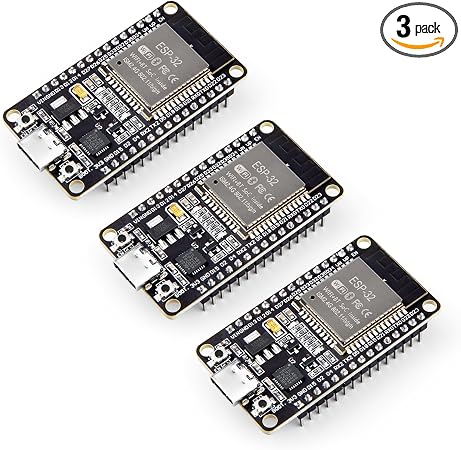
- Microcontroller: ESP32 Development Board WROOM – Dual-core, fast, and capable of I2S audio input.
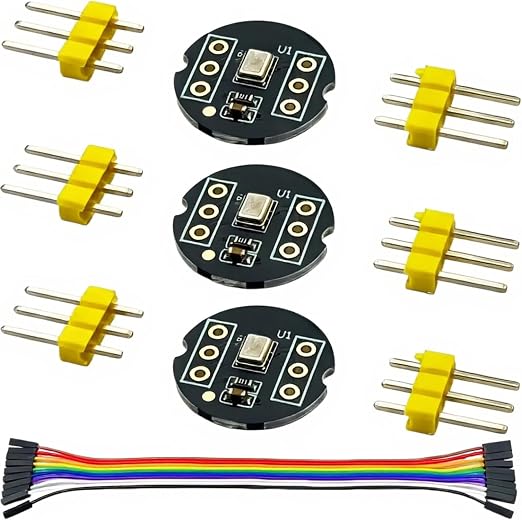
- The “Ear”: INMP441 I2S Microphone Module – A digital microphone that gives us raw, unadulterated audio data.
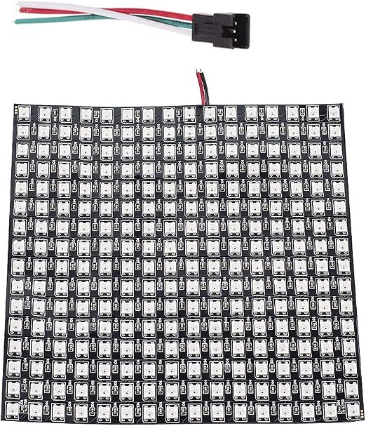
- The Display: WS2812B 16x16 LED Matrix Panel – 256 addressable NeoPixels.
- Power: A 5V, 10A (or higher) Power Supply. Do not power the matrix from the ESP32!
- Prototyping: Breadboard and premium jumper wires (see our Breadboards Showdown).
⚡ Step 1: The Power Problem (Don’t Fry Your Board)
Before we wire a single data line, we need to talk about power. A 16x16 WS2812B matrix contains 256 LEDs. If you turn them all to full white brightness, they can draw over 15 Amps.
If you try to pull that through your ESP32’s 5V pin, you will instantly fry the voltage regulator.
- Connect your 5V, 10A power supply directly to the power injection wires on the LED matrix.
- Connect the ESP32’s
VIN(or5V) pin to the 5V supply, and theGNDpin to the power supply’s ground. - Crucial Rule: The ESP32 and the LED matrix MUST share a common ground. If they don’t, your LEDs will flash randomly. (Read up on WS2812B troubleshooting if you run into glitching).
🎤 Step 2: Wiring the INMP441 Digital Mic
The INMP441 isn’t a normal analog sensor. It uses I2S (Inter-IC Sound), a digital protocol designed specifically for streaming audio. It requires three pins to work: Word Select (WS), Serial Clock (SCK), and Serial Data (SD).
ESP32 to INMP441 Connections:
- VDD $\rightarrow$ 3.3V (Do NOT use 5V!)
- GND $\rightarrow$ GND
- L/R $\rightarrow$ GND (Sets the mic to the left channel)
- WS (Word Select) $\rightarrow$ GPIO 15
- SCK (Serial Clock) $\rightarrow$ GPIO 14
- SD (Serial Data) $\rightarrow$ GPIO 32
💡 Step 3: Wiring the LED Matrix
We only need one data pin to control all 256 LEDs, thanks to the magic of the WS2812B protocol.
- LED Matrix DIN $\rightarrow$ ESP32 GPIO 13 (Put a 330-ohm resistor inline if you have one to protect the data pin).
- LED Matrix 5V & GND $\rightarrow$ Direct to the 5V power supply.
🧠 Step 4: The Code (FastLED & ArduinoFFT)
To make this work, you’ll need to install two libraries in your Arduino IDE:
- FastLED (by Daniel Garcia)
- arduinoFFT (by Enrique Condes)
The code uses the Fast Fourier Transform (FFT) to convert the raw audio waveform over time into a spectrum of frequencies (bass on the left, treble on the right).
Here is the core setup to get your I2S and FastLED initialized.
#include <driver/i2s.h>
#include <FastLED.h>
#include "arduinoFFT.h"

#define LED_PIN     13
#define NUM_LEDS    256
#define BRIGHTNESS  50
#define LED_TYPE    WS2812B
#define COLOR_ORDER GRB
CRGB leds[NUM_LEDS];

// I2S Microphone Pins
#define I2S_WS 15
#define I2S_SCK 14
#define I2S_SD 32

const i2s_port_t I2S_PORT = I2S_NUM_0;

void setup() {
  Serial.begin(115200);

  // Initialize FastLED
  FastLED.addLeds<LED_TYPE, LED_PIN, COLOR_ORDER>(leds, NUM_LEDS).setCorrection(TypicalLEDStrip);
  FastLED.setBrightness(BRIGHTNESS);

  // I2S Configuration
  i2s_config_t i2s_config = {
    .mode = (i2s_mode_t)(I2S_MODE_MASTER | I2S_MODE_RX),
    .sample_rate = 44100,
    .bits_per_sample = I2S_BITS_PER_SAMPLE_32BIT,
    .channel_format = I2S_CHANNEL_FMT_ONLY_LEFT,
    .communication_format = I2S_COMM_FORMAT_I2S,
    .intr_alloc_flags = ESP_INTR_FLAG_LEVEL1,
    .dma_buf_count = 8,
    .dma_buf_len = 1024,
    .use_apll = false,
    .tx_desc_auto_clear = false,
    .fixed_mclk = 0
  };

  i2s_pin_config_t pin_config = {
    .bck_io_num = I2S_SCK,
    .ws_io_num = I2S_WS,
    .data_out_num = I2S_PIN_NO_CHANGE,
    .data_in_num = I2S_SD
  };

  i2s_driver_install(I2S_PORT, &i2s_config, 0, NULL);
  i2s_set_pin(I2S_PORT, &pin_config);
}

void loop() {
  // FFT Processing logic goes here...
}
Note: The complete, multi-tab Arduino code with the FFT rendering logic is massive. You can find the full script in the Electron Parade GitHub Repository.
🎉 The Result
Once you flash the code and turn on the tunes, the ESP32 samples the audio at 44.1kHz, slices it into frequency bins using FFT, and maps the amplitudes to the height of the columns on your WS2812B matrix.
It’s mesmerizing. It’s mathematically beautiful. And most importantly, it’s not just a single LED having a seizure.
Got questions or ran into issues? Drop a comment below, or check out our Troubleshooting section if your serial monitor is throwing errors!