You’ve spent three hours carefully soldering a massive array of WS2812B LEDs, writing the perfect FastLED animation, and preparing for a glorious light show. You power it up, and instead of a smooth, majestic rainbow, your strip looks like it’s having a violent seizure. LEDs are flashing bright white, jumping between random colors, and completely ignoring your code.
Before you throw the whole spool in the trash or assume you burned them out with your soldering iron, take a breath. Your LEDs are probably fine. The magic blue smoke is still safely contained inside. The problem is almost certainly how you’re communicating with them.
Here are the three reasons your Neopixels are glitching, and how to fix them.
1. The 3.3V Logic Level Problem (The Most Common Culprit)
If you are using an ESP32, ESP8266, Raspberry Pi Pico, or any modern 3.3V microcontroller, this is your problem.
WS2812B LEDs run on 5V. According to their datasheet, the data line (DIN) requires a voltage of at least 0.7 × VDD to register a “HIGH” signal.
If your power supply is giving the LEDs exactly 5.0V, then:
5.0V × 0.7 = 3.5V
Your ESP32 only outputs 3.3V on its data pins. 3.3V is less than 3.5V. Sometimes it works because the voltage tolerances vary. But if your power supply is pushing 5.2V, the required threshold jumps to 3.64V, and your 3.3V signal is completely ignored or misread as random static (hence the glitching colors).
The Fix: Use a Logic Level Shifter
You need to step up your 3.3V data signal to a solid 5V signal. Do not use a standard transistor for this, as the WS2812B protocol requires high-speed timing (800kHz).
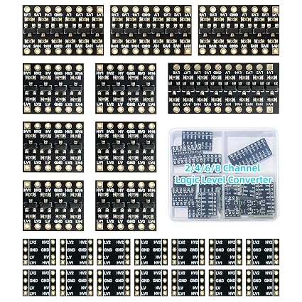
Instead, use a dedicated I2C Logic Level Converter (like the TXS0108E or standard bi-directional shifters).
- Connect the
LVside to 3.3V and your microcontroller’s data pin. - Connect the
HVside to 5V and route the shifted output to the LED strip’sDINpin. - Make sure all grounds are tied together!
2. Missing Ground Reference
Electricity requires a complete circuit. If you are powering your LED strip from a separate, hefty 5V power supply (which you should be!), and your Arduino/ESP32 is plugged into your laptop via USB, they have two different power sources.
If you only connect the Data pin to the strip, the microcontroller and the strip don’t share a common Ground reference. The data signal is essentially floating relative to the LED strip’s power.
The Fix: Connect the Grounds
Take a wire and connect a GND pin on your microcontroller to the GND / - terminal on your external 5V power supply. This gives the data signal a common baseline to reference against.
3. Voltage Spikes and Ringing (The Missing Components)
Long wires act like antennas and inductors. When sending high-speed data down a wire, the signal can “bounce” back and forth, creating “ringing” that confuses the first LED.
Additionally, when a large string of LEDs suddenly turns on full white, they suck a massive amount of current instantly. This causes a sudden voltage drop that can reset the microcontroller or corrupt the data.
The Fix: The Holy Trinity of LED Protection
If you want an industrial-strength, bulletproof LED setup, always include these two components:
- A Data Resistor: Place a
330Ωto470Ωresistor in series on the data line, as close to the first LED as possible. This dampens the ringing and protects the first LED’s data pin from voltage spikes. - A Big Capacitor: Place a large 1000µF 16V Electrolytic Capacitor across the 5V and GND lines, right where they connect to the LED strip. This acts as a localized reservoir of power, smoothing out the sudden current demands and keeping the voltage stable. (Reminder: Electrolytic capacitors are polarized. Connect the stripe side to Ground!)
Add the logic level shifter, the data resistor, and the smoothing capacitor, and your WS2812B setup will be flawless. Happy coding!