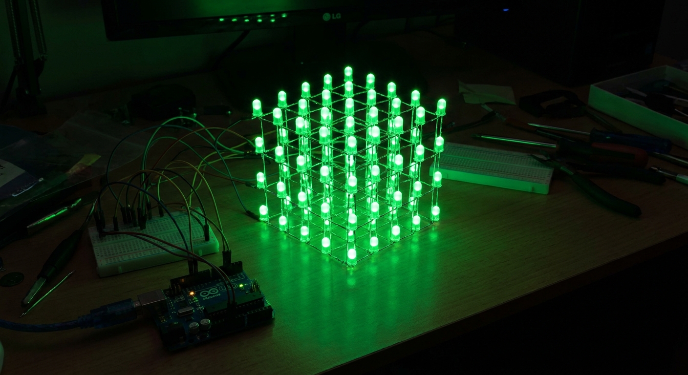
Welcome to Project 37! You’ve mastered basic LEDs and breadboarding. Now, it’s time to test your patience and soldering skills by building a visually stunning 4x4x4 LED Cube. At first glance, controlling 64 individual LEDs on an Arduino Uno seems impossible. The secret is multiplexing, a technique that requires you to solder a fragile, geometric nightmare of wire that will absolutely test your sanity.
The Magic of Multiplexing
Instead of wiring every single LED to a separate pin, we arrange them into a grid of 16 columns and 4 layers. All the positive legs (anodes) in a vertical column are connected together. All the negative legs (cathodes) in a horizontal layer are connected together.
By rapidly turning on one layer at a time and lighting up specific columns in that layer, our eyes perceive a persistent 3D image due to persistence of vision. We only need 16 pins for the columns and 4 pins for the layers (20 pins total, which fits perfectly by using the analog pins as digital outputs!).
Required Components
- Arduino Uno R3: The brain of your cube. Buy on Amazon
- 5mm Diffused Green LEDs (1000pcs): You need exactly 64, but buy a bulk pack. You’ll make mistakes, need spares, and definitely use them in future projects. Diffused LEDs are highly recommended because clear LEDs only look bright from the top. Buy on Amazon
- 2N2222 NPN Transistors (x4): To handle the current of switching an entire layer (up to 16 LEDs) at once.
- 220Ω Resistors (x16): For current limiting on the columns.
- 10kΩ Resistors (x4): For the transistor base pins.
- Perfboard & Hookup Wire: For soldering everything together securely.
Step 1: Building the Layers
The hardest part of this project is the physical construction. Start by drilling a 4x4 grid of 5mm holes into a piece of scrap wood, spaced about 1.5 cm apart. This will act as your soldering jig.
- Bend the cathode (shorter) leg of every LED 90 degrees.
- Place 16 LEDs into your jig.
- Solder all the bent cathodes together to form a solid grid. This is your first “layer.”
- Repeat this process three more times to create four identical layers.
Step 2: Stacking the Cube
Next, stack the layers vertically. Solder the anode (longer) legs of each LED to the anode of the LED directly below it. Take your time and use needle-nose pliers to keep the columns perfectly straight.
If you encounter issues where LEDs don’t turn on, use your multimeter (Lesson 109: Meet the Multimeter) to check for continuity or cold solder joints.
Step 3: Wiring the Circuit
Once the cube is built, solder it to a perfboard.
- Connect the 16 vertical columns to Arduino pins 0 through 13, plus Analog pins A0 and A1. (Don’t forget the 220Ω current-limiting resistors!)
- Connect the 4 horizontal layers to the collectors of your 2N2222 transistors.
- Connect the emitters of the transistors to GND.
- Connect the bases of the transistors through 10kΩ resistors to Arduino pins A2, A3, A4, and A5.
For a deep dive into the schematic and detailed visual wiring diagrams, refer to this excellent guide at PCBSync.
Step 4: The Code
Programming a 3D cube from scratch can be math-heavy. Most makers use a library or predefined byte arrays to animate patterns.
Here is a simplified snippet of how layer multiplexing looks in code:
// Pseudocode for Multiplexing
void loop() {
  for (int layer = 0; layer < 4; layer++) {
    // 1. Turn OFF all layers
    clearLayers();

    // 2. Set the 16 column pins for the current layer's pattern
    setColumns(currentPattern[layer]);

    // 3. Turn ON the current layer
    digitalWrite(layerPins[layer], HIGH);

    // 4. Wait a fraction of a millisecond
    delayMicroseconds(2000);
  }
}
By changing currentPattern rapidly, you can create falling rain, expanding boxes, and spinning spirals!
Next Steps
Once your 4x4x4 cube is working, the natural progression is to build an 8x8x8 cube! An 8x8x8 cube has 512 LEDs, which requires shifting techniques we covered in Lesson 132: Shift Registers. But for now, enjoy your mesmerizing new desk piece!