ElectronParade
Lesson 109: Meet the Multimeter
Welcome back to the Electron Parade Academy! In our last lesson, we learned how to build circuits on a solderless breadboard. But what happens when you build a circuit and it doesn’t work? Or you find a random battery in a drawer and don’t know if it has any juice left?
Enter the Digital Multimeter (DMM)—the absolute most important tool on your electronics workbench.
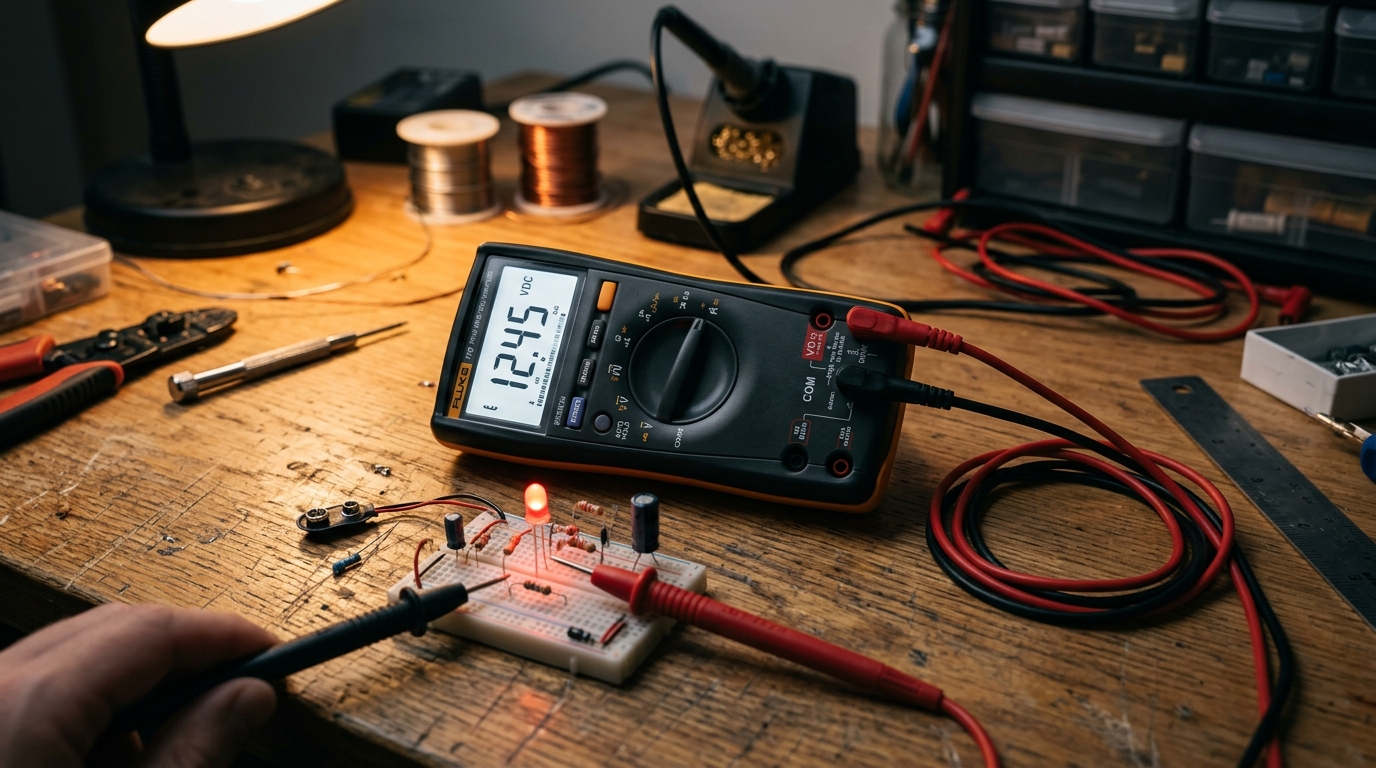 A digital multimeter is the ‘eyes’ that allow you to see invisible electricity.
What is a Multimeter?
Electricity is invisible. You can’t look at a wire and see how much voltage is flowing through it, or look at a resistor to confirm it isn’t broken inside. A multimeter gives you the ability to “see” electricity.
It’s called a multi-meter because it combines several different measurement tools into one device. While advanced meters have many features, almost every multimeter on the market measures three fundamental properties:
- Voltage (Volts): Measures the “pressure” of the electricity.
- Current (Amps): Measures the “flow” rate of the electricity.
- Resistance (Ohms): Measures how much a component resists the flow of electricity.
[Looking for your first meter? We highly recommend the AstroAI Digital Multimeter for beginners—it’s incredibly reliable and won’t break the bank.]
The Anatomy of a Multimeter
When you look at a standard multimeter, it can seem intimidating, but it breaks down into four main parts:
1. The Display
This is simply the screen where your measurements are shown. Modern meters use digital LCD screens (hence, Digital Multimeter).
2. The Selection Dial
This is the large rotary switch in the center. You turn this dial to tell the meter what you want to measure (Voltage, Current, or Resistance).
On many entry-level meters, you’ll also notice multiple numbers around each setting. This is called a Manual Ranging meter. You have to select the range slightly higher than what you expect to measure. For example, to measure a 9V battery, you would turn the dial to the “20V” setting.
Pro-tip: If you see a “1” or “OL” (Over Load) on the screen, it means the value you are measuring is higher than the range you selected. Turn the dial to a higher number!
3. The Ports
At the bottom of the meter, there are typically three or four holes where you plug in your probes.
- COM (Common): This is the ground connection. The black probe always plugs in here.
- mAVΩ (or similar): This is the main measuring port. The red probe plugs in here for measuring Voltage, Resistance, and small amounts of Current (milliamps).
- 10A (or similar): This port is only used when measuring large amounts of current (up to 10 Amps). If you are just starting out, you likely won’t use this port very often.
4. The Probes
Your meter comes with two wires, one red and one black, ending in metal tips. These are your test probes. You touch these tips to the circuit or component you want to measure. The color coding is standard across electronics: Red is for positive (+), Black is for negative/ground (-).
Your First Measurement: Testing a Battery
The easiest way to get comfortable with your new meter is to test some batteries around your house.
- Plug the black probe into the COM port.
- Plug the red probe into the VΩmA port.
- Turn the dial to measure DC Voltage. (Look for a ‘V’ with a straight line and a dashed line next to it. Do not select the ‘V’ with a squiggly line—that is for AC voltage from your wall outlet!)
- Set the range to 20V (since most household batteries are 1.5V or 9V, setting the meter to a max of 20V is perfect).
- Touch the black probe to the flat negative (-) side of an AA battery.
- Touch the red probe to the bumpy positive (+) side of the battery.
Look at the screen! A brand new AA battery should read around 1.5V or 1.6V. If it reads 1.2V or lower, it’s dead and should be recycled.
What if the screen shows a negative number, like -1.5V? Don’t panic! It just means you have the probes backward. The meter is still reading the correct voltage, it’s just telling you the polarity is reversed.
Up Next
Measuring voltage is just the beginning. In upcoming lessons, we’ll dive into measuring resistance, testing for continuity (checking if a wire is broken), and the slightly more complex process of measuring current. But for now, grab your meter and start checking those batteries!