ElectronParade
Lesson 132: Multiplying Outputs - Using the 74HC595 Shift Register
Your Arduino Uno has 14 digital I/O pins. That might seem like a lot when you’re just blinking a single LED or reading a single button. But what if you want to build an LED cube, a digital clock, or a scrolling text display? You will quickly run out of pins.
Instead of buying a larger, more expensive microcontroller, you can use a clever integrated circuit called a Shift Register.
 A shift register acts like an expansion module, turning a few control pins into many output pins.
What is a Shift Register?
The 74HC595 is one of the most famous shift registers. It takes serial data (data sent one bit at a time, sequentially down a single wire) and converts it into parallel data (multiple bits output simultaneously across multiple wires).
In practical terms: you use just three pins on your Arduino to talk to the 74HC595, and the 74HC595 gives you eight new digital output pins! Even better, you can “daisy-chain” multiple shift registers together. Connect two 74HC595 chips, and you get 16 outputs, still using those same original three Arduino pins.
What You’ll Need
- An Arduino board (like the ELEGOO UNO R3)
- A 74HC595 Shift Register IC (Available here)
- 8x LEDs (Any color)
- 8x 220-ohm Resistors
- Jumper Wires and a Breadboard
Understanding the Pins
The 74HC595 has 16 pins. The three critical pins connected to the Arduino are:
- Data Pin (DS, Pin 14): This is where the Arduino sends the 1s and 0s.
- Clock Pin (SHCP, Pin 11): The Arduino pulses this pin to tell the shift register, “I just put a new bit on the Data Pin, read it now!”
- Latch Pin (STCP, Pin 12): Once all 8 bits are loaded in, the Arduino pulses the latch pin to say, “Push those 8 bits to the actual output pins all at once.”
Wiring It Up
Wiring 8 LEDs can be messy, so take your time!
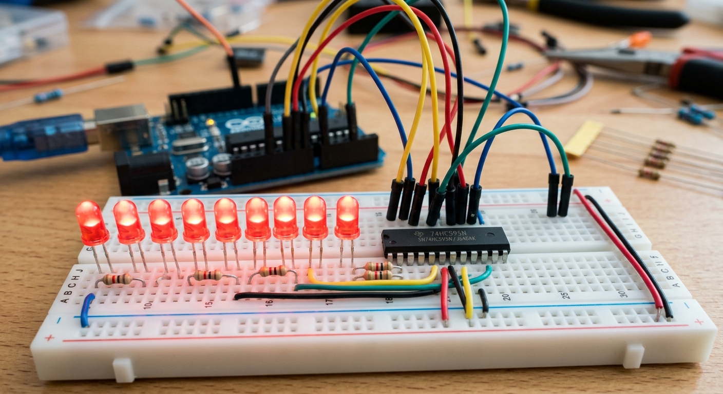
- Place the 74HC595 across the center trench of your breadboard. The small notch or dot on one end indicates the top (Pin 1 is top-left).
- Connect Pin 8 (GND) and Pin 13 (Output Enable) to the breadboard’s ground rail.
- Connect Pin 16 (VCC) and Pin 10 (Master Reclear) to the breadboard’s 5V rail.
- Connect the Arduino control pins:
- Arduino Pin 11 to 74HC595 Pin 14 (Data)
- Arduino Pin 12 to 74HC595 Pin 11 (Clock)
- Arduino Pin 8 to 74HC595 Pin 12 (Latch)
- Connect the 8 output pins (Q0 through Q7) to the positive legs of your 8 LEDs, with a 220-ohm resistor in series for each.
The Code: Shifting Bits
Here is the code to make the LEDs light up in a sequence using the shiftOut() function built into Arduino.
// Define the pins connected to the 74HC595
const int latchPin = 8;  // STCP
const int clockPin = 12; // SHCP
const int dataPin = 11;  // DS

void setup() {
  pinMode(latchPin, OUTPUT);
  pinMode(clockPin, OUTPUT);
  pinMode(dataPin, OUTPUT);
}

void loop() {
  // Loop through all 8 LEDs
  for (int i = 0; i < 8; i++) {
    // Ground the latch pin so the LEDs don't flicker while transmitting
    digitalWrite(latchPin, LOW);

    // Shift out a byte (8 bits).
    // bit(i) creates a byte with only the i-th bit set to 1.
    shiftOut(dataPin, clockPin, MSBFIRST, bit(i));

    // Pulse the latch pin high to push the data to the outputs
    digitalWrite(latchPin, HIGH);

    delay(200); // Wait so we can see the LED
  }
}
By mastering the shift register, you unlock the ability to build massive LED displays and complex indicators without worrying about running out of pins!