ElectronParade
Project 2: DIY Water Level Indicator (Two Ways)
Have you ever wondered how coffee makers or smart water tanks know when they are full? They use a principle you already know: water conducts electricity. (Technically, the minerals and impurities in the water conduct electricity, but the result is the same!)
Today, we’re building a simple Water Level Indicator. We are going to show you two different ways to build it. Why two? Because comparing them is the best way to understand one of the most important components in all of electronics: The Transistor.
Method 1: The Transistor-Less Approach (Direct Circuit)
The simplest way to detect water is to use the water itself as a switch in your circuit.
- Take a 9V battery and connect the positive wire to the very bottom of a plastic cup.
- Take a standard 5mm Red LED, connect a 330Ω (ohm) resistor to its long leg (anode), and attach a wire to the other end of the resistor.
- Tape this wire halfway up the inside of the cup.
- Connect the short leg of the LED back to the battery’s negative terminal.
When you pour water into the cup and it touches the halfway wire, the water completes the circuit between the bottom wire and the halfway wire. Electricity flows, and the LED turns on!
The Problem: Water is a terrible wire. It has very high electrical resistance. Because the electricity has to fight its way through the water to reach your LED, the LED will likely be extremely dim. If you tried to use a loud buzzer instead of an LED, it might not have enough power to make a sound at all.
(You can see a full breakdown of a direct, transistor-less build in this Instructable by TheDiyWorld.)
Method 2: The Transistor-Based Approach (The Amplifier)
To fix our dim LED problem, we need a way to use the tiny trickle of electricity coming through the water to control a large flow of electricity coming straight from the battery. Enter the BC547 NPN Transistor.
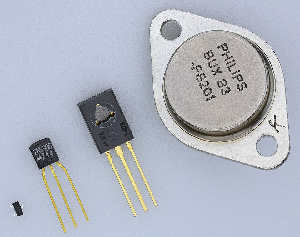 Transistors come in many shapes and sizes (called “packages”) depending on how much power they handle. On the left is the small plastic TO-92 package (like our BC547, used for low-power signals). In the middle are TO-126 and TO-220 packages (which feature metal tabs to attach heat sinks for medium power). On the right is the large, all-metal TO-3 package, designed to dissipate heat in heavy-duty, high-power applications.
A standard NPN transistor has three legs: the Collector, the Base, and the Emitter. Think of it like a plumbing valve:
- Collector: Where the high-pressure water (full battery power) sits waiting.
- Emitter: Where the water flows out to power your LED or buzzer.
- Base: The valve handle.
Here is how we wire the upgraded version using a BC547 NPN Transistor:
- Connect the short leg of a 5mm Red LED to the transistor’s Collector.
- Connect a 330Ω resistor from the LED’s long leg to the 9V battery’s positive terminal.
- Connect the transistor’s Emitter to Ground (the battery’s negative terminal). (The circuit is currently “off” because the transistor valve is closed).
- Run a wire from the 9V battery’s positive terminal to the bottom of the cup.
- Run a wire from the halfway point of the cup, connect it to a 1kΩ resistor, and connect the other end of that resistor to the Base of the BC547 transistor. (The 1kΩ resistor protects the transistor from drawing too much current if the water is highly conductive).
How it works: When the water hits the halfway mark, a tiny, weak electrical current flows through the water and hits the Base pin. That tiny current “opens the valve.” Suddenly, the transistor allows the full, strong current to flow from the Collector to the Emitter. Your LED shines at full brightness, or your buzzer screams at full volume!
(For a step-by-step guide on wiring this up on a breadboard, check out this Water Level Alarm Instructable by ptkrf.)
Why This Matters
By building both of these circuits, you’ve just learned why transistors exist. They are the fundamental building blocks of modern computers because they allow weak signals (like a sensor reading) to control powerful outputs.
Grab your breadboard, a cup of water, and try building both!