ElectronParade
Lesson 108: Breadboards and Prototyping Basics
Welcome to Lesson 108! In previous lessons, we covered the theory of components like resistors, capacitors, and LEDs. Today, we’re getting hands-on with the most essential tool for any electronics beginner: The Solderless Breadboard.
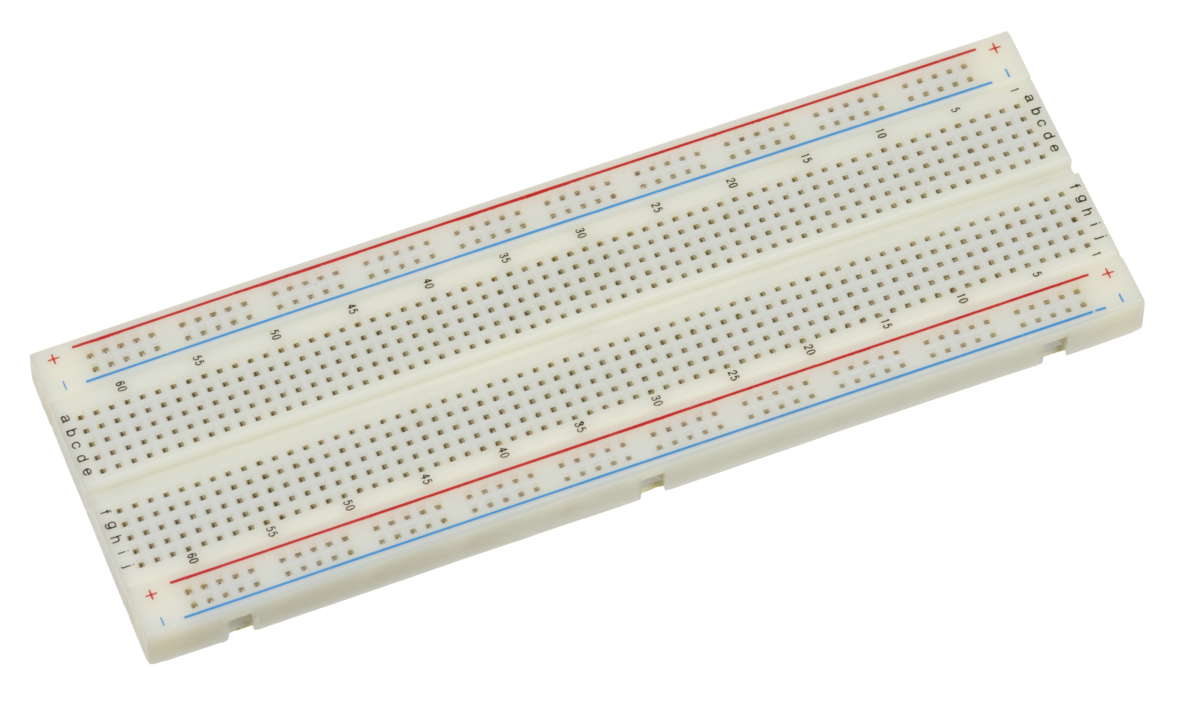 A standard solderless breadboard, the perfect sandbox for building circuits.
What is a Breadboard?
A breadboard is a construction base for prototyping electronic circuits. The name comes from the early days of electronics when hobbyists would actually hammer nails into wooden boards used for cutting bread to connect their wires. Thankfully, modern breadboards don’t require power tools—or bread.
Today’s breadboards are plastic blocks filled with a grid of holes spaced exactly 0.1 inches (2.54mm) apart. You just push wires and component legs into the holes, and they connect instantly. Best of all? No soldering required. If you make a mistake, simply pull the wire out and try again.
Inside the Board: How It Actually Works
If you were to peel the sticky foam backing off the bottom of a breadboard, you wouldn’t see wires. Instead, you would see rows of stamped metal strips.
Each strip has a series of tiny spring-loaded clips. When you push a wire into a hole on the top of the breadboard, you are forcing it into one of these metal clips. Because the clips are part of a continuous metal strip, anything plugged into that same strip becomes electrically connected.
How the Holes Connect
When you look at the top of a breadboard, it looks like a sea of holes. But based on those metal strips underneath, they are connected in a very specific pattern:
1. The Power Rails (Bus Strips)
Along the very top and very bottom (the long edges), you’ll see long rows of holes usually marked with a red line (+) and a blue or black line (-).
- These are the Power Rails.
- Every hole along the red line is connected to every other hole on that red line.
- You use these to distribute your power (e.g., from a battery or an Arduino) to the rest of the board so you can easily tap into power from anywhere.
2. The Terminal Strips (Component Rows)
In the middle, you have short rows of five holes, usually labeled with numbers (1, 2, 3…) down the side and letters (a, b, c, d, e) across the top.
- These holes are connected horizontally.
- Holes
1a, 1b, 1c, 1d, 1eare all the exact same piece of metal underneath. If you plug a resistor into1aand an LED into1e, they are electrically connected! - The connection stops at the gap in the middle of the board. The row
1f, 1g, 1h, 1i, 1jis separate from thea-eside.
The “Trench” (DIP Support)
Notice the ditch running down the center of the breadboard? That serves a very specific purpose. When we start using microchips (known as DIP or Dual In-line Package chips), we straddle them across this trench. This ensures the pins on the left side of the chip don’t accidentally connect to the pins on the right side, giving each pin its own independent row of 5 holes to connect wires to.
Breadboard Sizes
Breadboards come in a few standard sizes depending on your needs:
- Full-Size: Typically 830 tie-points. Great for complex circuits with multiple chips.
- Half-Size: Typically 400 tie-points. The most common size, perfect for Arduino projects and general prototyping.
- Mini: Typically 170 tie-points, with no power rails. Best for tiny, single-chip circuits or adding a tiny workspace onto a robot chassis.
Jumper Wires: Connecting It All Together
To connect different rows, you need jumper wires.
- Pre-formed solid core wire: These sit flush against the board, making your circuit look incredibly neat and professional. However, they take a bit more time to bend and place.
- Flexible jumper wires (Dupont cables): These have molded plastic pins on the ends. They are incredibly fast to plug in and move around, but your circuit can quickly look like a “rat’s nest” if you use too many. (Note: Always use solid-core wire. Stranded wire will fray and is nearly impossible to push into the breadboard’s clips!)
Making Your First Connection
To test your breadboard out, try this simple LED circuit:
- Connect your power supply’s positive lead to the red power rail.
- Connect your ground lead to the blue power rail.
- Place a resistor from the red rail to row 10 (hole
10a). - Place an LED’s long leg into row 10 (hole
10e), and its short leg into the blue ground rail. - Watch it light up! You’ve just built a circuit without a single drop of solder.
Common Beginner Mistakes
As you start building, watch out for these classic pitfalls:
- The “Same Row” Short: Plugging both legs of an LED or resistor into the same numbered row (e.g.,
1aand1c). Because the whole row is connected, the electricity will bypass the component entirely, creating a short circuit. Components must bridge across different rows. - Split Power Rails: On many full-size breadboards, the red and blue lines along the edge have a gap in the middle. This means the left half of the power rail is not connected to the right half. If you need power along the whole edge, you must use a small jumper wire to bridge that middle gap!
Limitations of Breadboards
While amazing for beginners and prototyping, breadboards aren’t perfect for everything:
- Current Limits: The metal clips are thin. If you run too much current through them (like powering large motors), they can melt the plastic.
- High Frequencies: The parallel metal strips running next to each other act like tiny capacitors. This “parasitic capacitance” can cause high-frequency circuits (like radio transmitters or high-speed data lines) to behave unpredictably.
Next Steps
Now that you know how to navigate the grid and avoid common pitfalls, it’s time to test your skills in the real world. Tomorrow, we’ll be putting these basics to work in our next project. Stay tuned!