Are your servo motors acting like they’ve had six shots of espresso? You upload a simple sweep sketch, and instead of a smooth rotation, your robot arm starts vibrating, twitching, and aggressively dancing across your desk like an angry maraca.
Don’t panic. You aren’t experiencing paranormal activity, and your code is probably fine. This is a classic case of power starvation. We’re going to fix it before your motors tear themselves apart and release the dreaded magic blue smoke.
The Problem: Why Do Servos Jitter?
When a servo motor moves, it draws a massive spike of current (often over 1 Amp for larger servos). If you have your servo connected directly to the Arduino’s 5V pin, it will try to pull that current through the microcontroller’s tiny onboard voltage regulator.
When the Arduino can’t provide enough juice fast enough, the voltage drops. This brownout causes the servo’s internal logic to reset, fail to read its position, twitch, try to move again, and cause another voltage drop. It’s an infinite loop of electrical panic.
Solution 1: External Power Supply (The Right Way)
Never power motors directly from an Arduino. You need an external power supply dedicated to the motors.
- Get a 5V 2A Power Supply Adapter.
- Connect the power supply’s positive (+) terminal directly to the servo’s VCC wire (usually red).
- Connect the negative (-) terminal to the servo’s GND wire (usually brown or black).
- CRITICAL STEP: You MUST connect the ground of your external power supply to the
GNDpin on your Arduino. If they don’t share a common ground, the control signal won’t work, and you’ll get floating pins.
Solution 2: The Decoupling Capacitor (The Band-Aid)
If you’re using a single, small micro-servo (like an SG90) and you’re still seeing occasional jitters, you can add a decoupling capacitor across the power lines.
- Grab a large capacitor from your 1000uF Electrolytic Capacitor Kit.
- Place it across the 5V and GND rails on your breadboard as close to the servo connection as possible.
- Warning: Electrolytic capacitors are polarized. The longer leg goes to
5V, and the shorter leg (with the stripe on the side) goes toGND. Doing this backward will result in a loud pop and a face full of confetti.
This acts as a tiny battery reserve, smoothing out the voltage spikes when the servo initially draws current.
Solution 3: Offload the PWM Timing (The Pro Way)
If you are building a larger project with multiple servos, don’t rely on the Arduino’s Servo.h library to handle the timing for all of them.
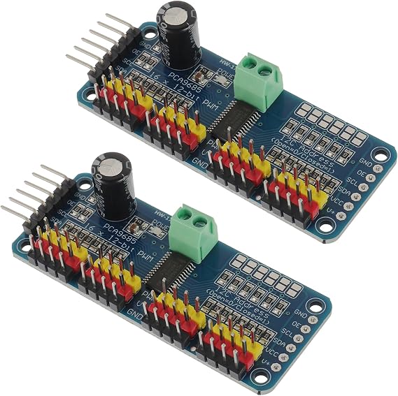
Instead, use an I2C controller like the PCA9685 16-Channel Servo Driver. This board generates its own perfectly stable PWM signals and has a dedicated terminal block for your external power supply. It turns your spaghetti code into a smooth, professional operation.