Project 42: Build an ESP32-CAM AI Face Recognition Door Lock
We’ve all been there: you walk up to your front door carrying three bags of groceries, a lukewarm coffee you swore you’d finish, and a piece of mail that is definitely a bill. You don’t have a free hand to dig for keys. You try to awkwardly balance the coffee on your knee while rummaging through your pockets, and… disaster strikes. The coffee spills, the groceries tumble, and you’re left standing on your porch re-evaluating your life choices.
Keys are a primitive technology for primitive times. It’s 2026. Your phone unlocks by looking at you; your door should do the same.
Today, we are going to build a smart, biometric door lock using the ESP32-CAM. We’ll program it to scan a video feed, recognize your specific face (and ignore your shady roommate), and fire a heavy-duty 12V solenoid to pop the door open automatically. No magic blue smoke, no dropped groceries—just pure, futuristic convenience.
(Note: We built an RFID Door Lock back in Project 16, but this takes security up a notch by relying on biometrics instead of a plastic tag that can be stolen!)
The Core Concept: How Does It Work?
The ESP32-CAM is a tiny, $10 microcontroller that features built-in Wi-Fi and a camera interface (usually paired with an OV2640 sensor). Espressif (the company that makes the ESP32) provides an incredible camera web server example out of the box that includes facial detection and recognition algorithms built right in.
Here’s the flow:
- The ESP32-CAM streams a video feed.
- The onboard AI looks for a human face.
- If it finds one, it compares the geometry of that face to the faces stored in its memory (enrolled faces).
- If it finds a match, it sets a GPIO pin
HIGH. - That GPIO pin triggers a relay or MOSFET, which allows a beefy 12V power supply to actuate the solenoid lock, pulling the deadbolt back.
What You Will Need
To build this facial recognition lock, you’ll need the following gear. (Note: The ESP32-CAM doesn’t have a built-in USB port, so you must use an FTDI programmer to upload the code!)
- ESP32-CAM Module with OV2640 Camera
- FTDI FT232RL USB to TTL Serial Converter (For programming)
- 12V Electric Solenoid Door Lock
- Relay Module (5V) (To safely switch the 12V lock)
- 12V Power Supply (At least 2 Amps to handle the solenoid’s initial draw)
- 5V Step-Down Converter (Buck Converter) (To power the ESP32-CAM from the 12V supply)
- Jumper wires, a breadboard, and some patience.
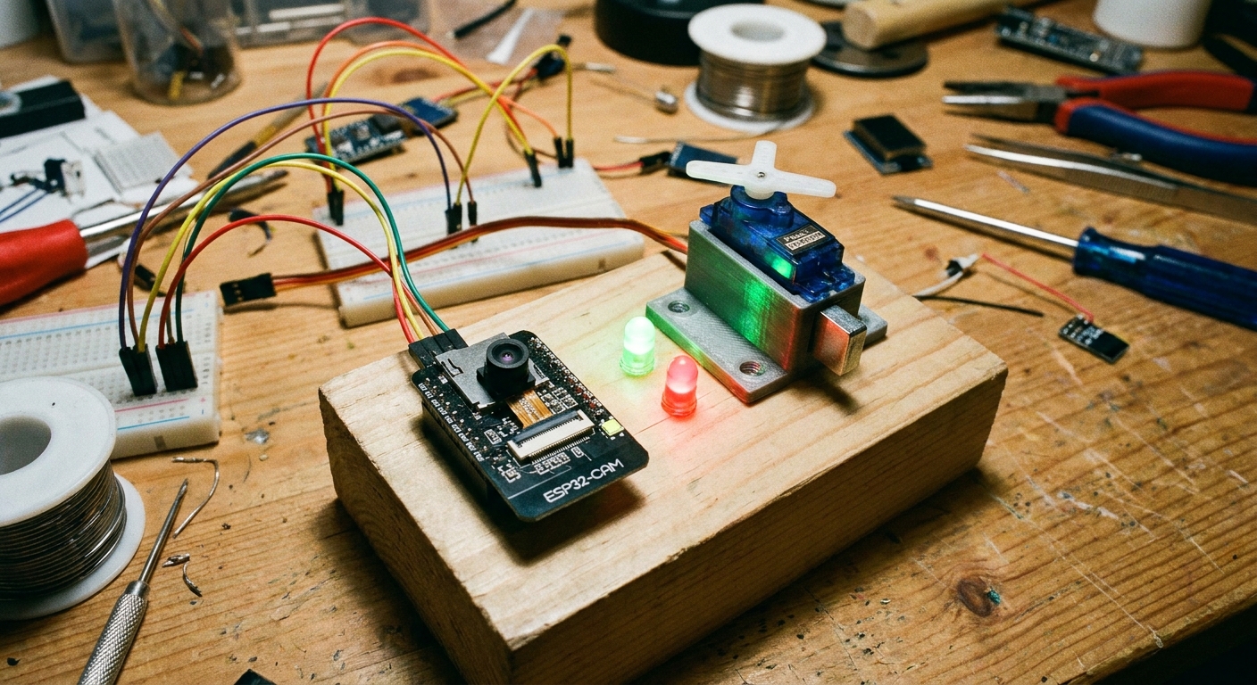
Step 1: The Circuit Wiring
This circuit is a tale of two voltages. We have the sensitive 5V logic of the ESP32-CAM and the brute-force 12V power required to move the heavy metal solenoid. We use a Relay to keep them safely separated.
Powering the System:
- Connect the positive (+) lead of your 12V power supply to the VIN of your 5V Buck Converter, and to the Common (COM) terminal of the Relay.
- Connect the ground (-) lead of your 12V power supply to the GND of the Buck Converter and the ground of the Solenoid.
- From the 5V Output of the Buck Converter, connect to the 5V pin on the ESP32-CAM and the VCC pin on the Relay module.
- Connect the GND of the Buck Converter to the GND pin on the ESP32-CAM and the GND pin on the Relay module.
Triggering the Lock:
- Connect GPIO 4 on the ESP32-CAM to the IN (Signal) pin on the Relay module. (Note: GPIO 4 is also connected to the onboard flash LED. When the lock triggers, the flash will briefly pulse, acting as a great visual indicator!)
- Connect the Normally Open (NO) terminal of the Relay to the positive wire of the 12V Solenoid.
Step 2: Preparing the Arduino IDE
Because the ESP32-CAM is doing some heavy lifting with AI, we need to ensure the Arduino IDE is set up correctly.
- Open the Arduino IDE. Go to File > Preferences and ensure the ESP32 board manager URL is added.
- Go to Tools > Board > Boards Manager, search for
esp32, and install it. - Select AI Thinker ESP32-CAM from the boards menu.
- CRITICAL: Under Tools > Partition Scheme, select Huge APP (3MB No OTA/1MB SPIFFS). The facial recognition libraries are massive and will not fit in the standard partition size.
Step 3: The Code (Modifying the Example)
We are going to use the official Espressif Camera Web Server example, but we need to inject a few lines of code to trigger our relay when a face is recognized.
- In the Arduino IDE, go to File > Examples > ESP32 > Camera > CameraWebServer.
- Near the top of the main sketch, uncomment
#define CAMERA_MODEL_AI_THINKERand comment out the other models. - Enter your Wi-Fi credentials:
const char* ssid = "YOUR_WIFI_NETWORK";
const char* password = "YOUR_WIFI_PASSWORD";- Define our lock pin at the very top:
int lockPin = 4; // Using GPIO 4 (Flash LED) to trigger the relay- Inside the
setup()function, configure the pin:
pinMode(lockPin, OUTPUT);
digitalWrite(lockPin, LOW); // Ensure the lock is engaged on startup
Modifying the Recognition Logic
The actual facial recognition logic happens in a secondary file called app_httpd.cpp. Look at the tabs at the top of your Arduino IDE and click on app_httpd.cpp.
Scroll down (or use Ctrl+F) to find the face_recognize function block. You are looking for a line that looks like this:
if (matched_id > 0) {
This is the exact moment the AI realizes it knows who you are. We need to inject our relay trigger right here. Modify the code block to look like this:
if (matched_id > 0) {
    Serial.printf("Match Face ID: %u\n", matched_id);

    // --- OUR CUSTOM LOCK LOGIC ---
    Serial.println("Face Recognized! Opening Door...");
    digitalWrite(4, HIGH); // Trigger Relay
    delay(3000);           // Keep door unlocked for 3 seconds
    digitalWrite(4, LOW);  // Lock door again
    // -----------------------------
} else {
    Serial.println("Match Face: Not Found");
}
Step 4: Uploading the Code (The Tricky Part)
The ESP32-CAM doesn’t have a USB port. You must use the FTDI adapter.
- Connect the FTDI to the ESP32-CAM:
- FTDI 5V -> ESP32 5V
- FTDI GND -> ESP32 GND
- FTDI TX -> ESP32 U0R (Receive)
- FTDI RX -> ESP32 U0T (Transmit)
- Put the board in flash mode: Use a jumper wire to connect GPIO 0 to GND on the ESP32-CAM.
- Plug the FTDI into your computer.
- Press the Reset (RST) button on the bottom of the ESP32-CAM board.
- Hit “Upload” in the Arduino IDE.
- Once it says “Hard resetting via RTS pin”, remove the jumper wire between GPIO 0 and GND and press the Reset button one more time to boot into normal operation.
Step 5: Enrolling Your Face
- Open the Serial Monitor (set baud rate to 115200).
- The serial monitor will output an IP address (e.g.,
http://192.168.1.100). - Open that IP address in your web browser.
- Click Start Stream at the bottom of the menu.
- Turn on Face Detection and Face Recognition.
- Stand in front of the camera and click Enroll Face. The camera will take several snapshots of your face to build a profile.
Once enrolled, the next time you step into the frame, the web interface will draw a green box around your face, print Hello Subject 0, and you’ll hear the satisfying THUNK of your 12V solenoid pulling back.
Welcome to the future. Now go pick up your spilled coffee.