ElectronParade
Project 20: Mini Arduino CNC Plotter
Have a couple of old, broken DVD or CD-ROM drives collecting dust? Don’t throw them out! Hidden inside those drives are highly precise, miniature stepper motors on sliding rails—the perfect mechanical foundation for a homemade CNC machine.
In this project, we are going to build a Mini Arduino CNC Plotter. We’ll extract the X and Y axis mechanisms from the optical drives, add a micro servo to lift a pen (the Z-axis), and use an Arduino Uno combined with an L293D Motor Drive Shield to control it all. By the end, your robot will be able to draw text and vector graphics right on your desk.
What You’ll Learn
- How to salvage and reuse electronic components from old hardware.
- The basics of CNC (Computer Numerical Control) machines.
- How to wire and control bipolar stepper motors.
- How to use G-Code to translate software images into physical hardware movements.
Parts Required
Here are the specific components used in this build:
- 1x Arduino Uno R3
- 1x L293D Motor Drive Shield
- 1x SG90 Micro Servo Motor
- 1x 12V 2A Power Supply Adapter
- 2x Old DVD/CD-ROM Drives (For the stepper motor sled mechanisms)
- Jumper Wires
- A Pen or Fine-Tip Marker
- Cardboard, Acrylic, or 3D Printed Parts (To build the chassis/frame)
- Hot Glue and Zip Ties
Step 1: Salvaging the Stepper Mechanisms
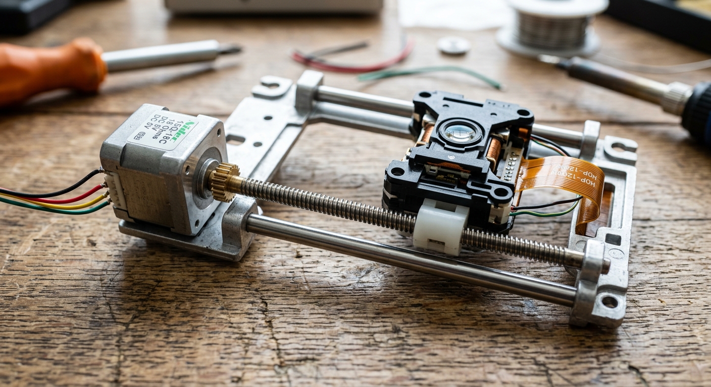
The first step involves a bit of destructive engineering. Open up your two old DVD drives and carefully extract the optical laser sleds. You’ll notice a small stepper motor attached to a threaded rod, which moves the laser back and forth.
- Cut the ribbon cables attached to the motors (leave enough length to solder jumper wires to them).
- The stepper motor will have 4 pins. Use a multimeter in continuity mode to figure out which pairs of pins belong to Coil A and Coil B.
Step 2: Building the Chassis
We need to mount our two axes perpendicularly.
- The Y-Axis (The Bed): Mount one of the DVD drive sleds flat on a sturdy base. Tape or glue a small platform (like a piece of CD or cardboard) to the moving part of the sled. This is where your paper will go.
- The X-Axis (The Bridge): Build a small bridge over the Y-axis and mount the second DVD sled horizontally across it.
- The Z-Axis (The Pen Holder): Attach the SG90 micro servo to the moving part of the X-axis sled. Fashion a small hinge or rail so the servo horn can lift and drop the pen onto the paper.
Step 3: Wiring the Motors
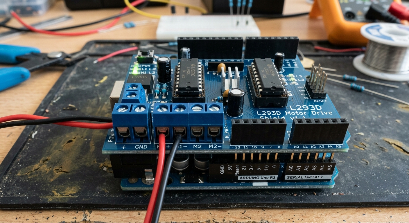
Stack the L293D Motor Shield onto your Arduino Uno.
- X-Axis Stepper: Connect the 4 wires of your X-axis motor to the M1 and M2 terminal blocks on the motor shield.
- Y-Axis Stepper: Connect the 4 wires of your Y-axis motor to the M3 and M4 terminal blocks.
- Z-Axis Servo: Plug the servo into the SERVO 1 header on the shield.
- Connect your external 12V power supply to the EXT_PWR terminals on the shield. Crucial: Remove the power jumper on the shield so you don’t fry your Arduino’s USB port!
Step 4: The Software (Grbl and G-Code)
To make this work, we won’t be writing an Arduino sketch from scratch. Instead, we use specialized firmware designed for CNC machines.
However, standard Grbl firmware is designed for dedicated CNC stepper drivers (like A4988s), not the L293D shield. Because of this, we must use a modified firmware called AFMotor Grbl or a custom processing script.
Here is the complete software stack you will need:
- Firmware: Download the custom GRBL for L293D / Servo repository from GitHub. Extract it, add it to your Arduino libraries, and upload the
grblUpload.inosketch to your Arduino. - Sender: Download a G-Code sender program like Universal Gcode Sender (UGS) to stream the instructions from your PC to the Arduino.
- Generator: Generate your G-Code files using Inkscape combined with the MakerBot Unicorn G-Code Output extension.
Step 5: Calibration and Plotting
Once the software is running:
- Turn on the power supply.
- Load a simple G-Code file into your Universal Gcode Sender.
- Watch as your upcycled optical drives magically recreate your digital drawing in the real world!
Pro-Tip: You may need to tweak the steps-per-millimeter in the software settings via UGS (e.g. $100 and $101 settings), as different DVD drive motors have slightly different thread pitches on their rods.
Enjoy your very own desktop robot artist!