ElectronParade
You’ve built your circuit. It works perfectly. The LEDs blink, the motors spin, and the sensors are reading data just as you intended. But there’s a problem: it’s on a breadboard.
Breadboards are phenomenal for rapid prototyping and testing, but they are not meant for permanence. Wires fall out if bumped, stray capacitance can ruin high-frequency signals, and the connections are fundamentally fragile. If you want to put your project inside a case, deploy it outside, or show it off without fear of it falling apart, you must learn to make it permanent.
Welcome to Module 9 of our journey: Making It Permanent (PCBs). In this lesson, we will cover how to transition a circuit from a breadboard to a protoboard (perfboard).
What is a Protoboard?
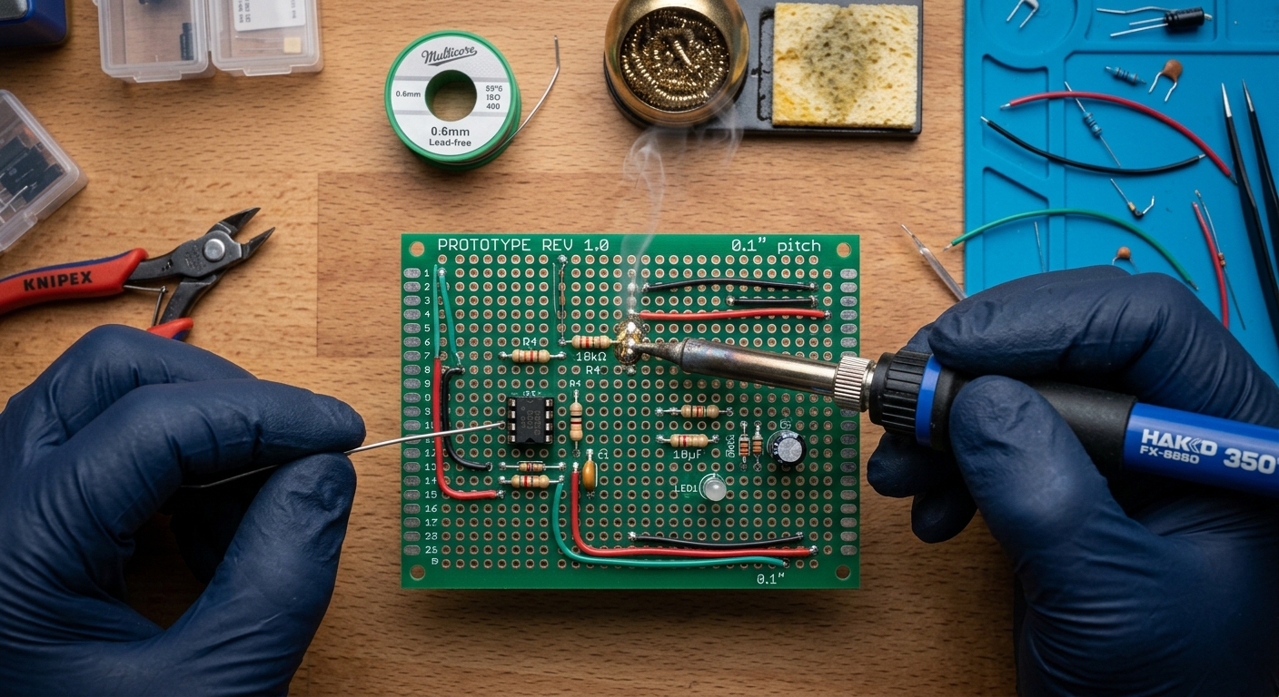
A protoboard (short for prototyping board) is a rigid fiberglass or paper-composite board peppered with a grid of holes. Each hole has a copper pad around it. Unlike a breadboard, where rows are internally connected by metal clips, a standard protoboard’s holes are entirely isolated.
To create a circuit on a protoboard, you push your component leads through the holes, solder them to the copper pads, and then bridge the necessary connections using wire or solder traces.
Step 1: Planning the Layout
Do not start soldering blindly. Once a component is soldered, moving it is tedious and risks damaging the board.
- Keep the Breadboard Intact: If possible, keep your working breadboard circuit built. Use it as a visual reference.
- Mirror the Layout: The easiest way to transition is to replicate your breadboard’s physical layout on the protoboard. Many protoboards even mimic a breadboard’s layout (featuring continuous power rails and 5-hole linked rows). If you are using one of these “breadboard-style” protoboards, the transition is almost 1:1.
- Group by Function: If you are using a standard “island” protoboard (where no holes are connected), try to group components by function. Keep decoupling capacitors close to the power pins of your ICs (Integrated Circuits), and route your power and ground lines first.
Step 2: Placement and Tack Soldering
- Insert your lowest-profile components first (like resistors and diodes).
- Bend the legs slightly outward on the bottom side of the board so the component stays in place when you flip the board over.
- Solder one leg of the component to “tack” it in place. Flip the board over and check if it’s flush and straight. If it’s crooked, simply reheat that single solder joint and straighten the component.
- Once it is perfectly seated, solder the remaining legs.
Step 3: Making Connections (Trace Routing)
Since a standard protoboard doesn’t have internal connections, you have to create them. There are two primary methods:
Method A: The Lead-Bending Technique (For short distances)
Instead of trimming the excess leads off your resistors and capacitors immediately, bend them flat against the bottom of the board toward the next component they need to connect to. Solder the lead across the intermediate pads to create a solid trace.
Method B: Hookup Wire (For longer distances)
For crossing the board, use solid-core wire (usually 22 AWG or 24 AWG). Strip the ends, push them through the holes next to the components you want to connect, and solder them together. Pro-Tip: Color-code your wires! Red for VCC, Black/Blue for GND, and Yellow/White for signal lines. This makes troubleshooting infinitely easier.
Advanced Soldering Tips
- Use Flux: Flux is a chemical cleaning agent that flows before the solder, removing oxidation and helping the solder stick to the pads. If your solder joints are clumping up or look dull, add a little flux paste or use a flux pen.
- The “Drag Soldering” Bridge: If you need to connect three adjacent holes, apply a generous amount of flux, add a blob of solder to your iron tip, and drag it across the pads. The flux will help the solder bridge the gap smoothly without creating sharp spikes.
- Clean Your Board: Once you are done, your board will likely be covered in sticky flux residue. Use a Q-tip dipped in high-concentration Isopropyl Alcohol (90%+) and an old toothbrush to gently scrub the back of the board.
What’s Next?
Transitioning to a protoboard is a massive leap in your electronics journey. Your projects will go from fragile desk experiments to durable gadgets. However, protoboards still require tedious point-to-point wiring.
In our next lesson, we will introduce EDA (Electronic Design Automation) software, where you will learn how to draw your circuits on a computer so you can have custom, professional printed circuit boards (PCBs) manufactured for you!