ElectronParade
Welcome to Lesson 172! After mastering individual sensors and motors over the past few modules, it is time for a major Capstone Project. We are going to build an autonomous Line Following Robot.
This project combines DC motor control, infrared (IR) reflection sensors, and conditional logic to create a robot that can “see” a black line on a white surface and steer itself to stay on track.
How It Works
A line following robot uses IR tracking sensors mounted on the front of its chassis, pointing straight down.
- White surfaces reflect the infrared light back into the sensor’s receiver.
- Black surfaces absorb the infrared light, meaning no light bounces back.
By using at least two sensors (one on the left, one on the right), the Arduino can constantly monitor the robot’s position relative to a thick black line:
- Both sensors see white: The robot is centered over the line (the line is between the sensors). Drive straight.
- Left sensor sees black: The robot is drifting to the right. Slow down or stop the left motor, and power the right motor to turn left back onto the line.
- Right sensor sees black: The robot is drifting to the left. Turn right to correct.
The Hardware You Will Need
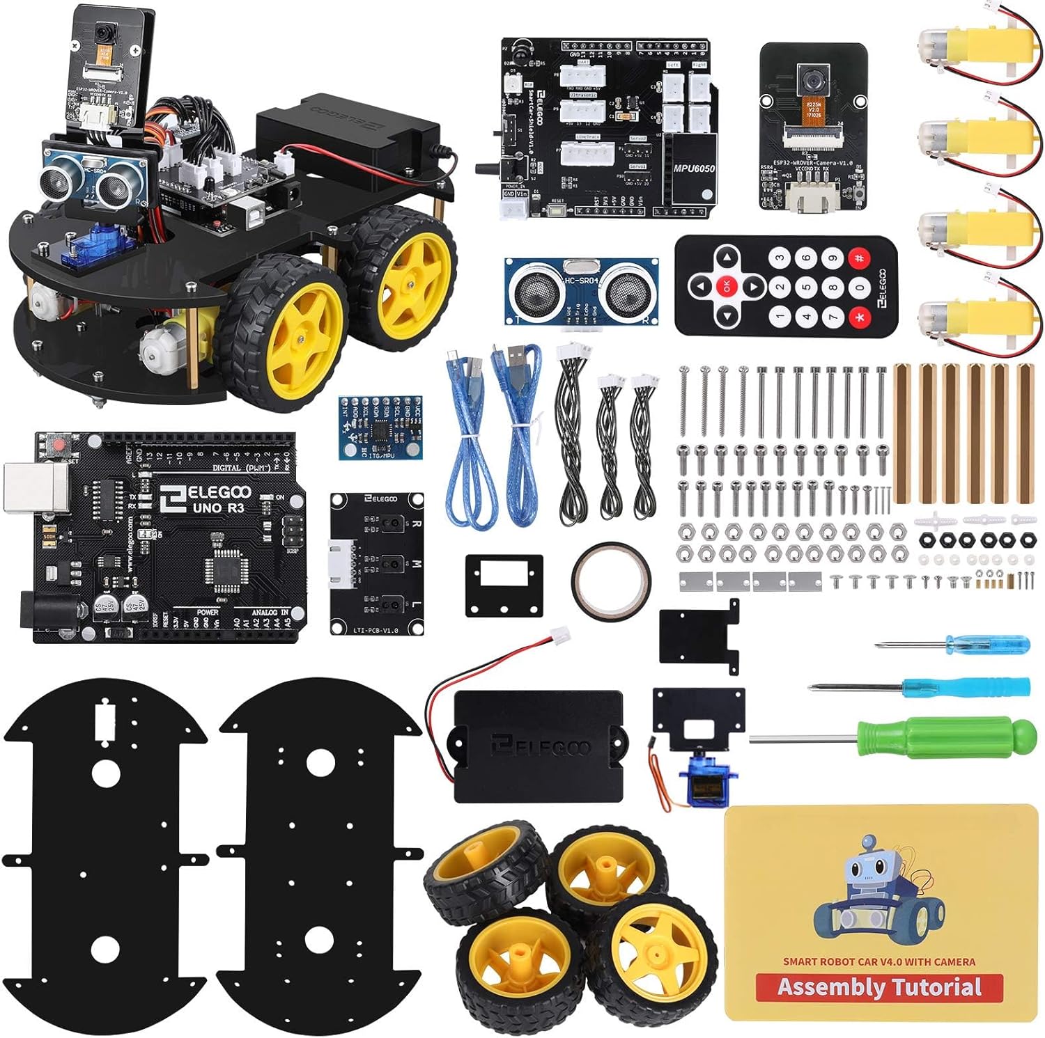
If you want to save time and guarantee compatible parts, we highly recommend checking out our Line Following Kits Showdown to pick up an all-in-one smart car kit like the Elegoo V4.
If you are building from scratch, you will need:
- 1x Arduino Uno
- 1x L298N Motor Driver
- 2x DC Gear Motors and Wheels
- 1x Robot Chassis (with a caster wheel for the front)
- 2x IR Tracking Modules (TCRT5000 based)
- 1x Battery Pack (e.g., 2x 18650 batteries or a 9V battery, though 9V is not recommended for motors)
- Jumper Wires
The Wiring
- IR Sensors:
- Left IR Sensor: Connect VCC to 5V, GND to GND, and OUT to Arduino Digital Pin 2.
- Right IR Sensor: Connect VCC to 5V, GND to GND, and OUT to Arduino Digital Pin 3.
- Motor Driver (L298N):
- Connect the two left motor wires to OUT1 and OUT2.
- Connect the two right motor wires to OUT3 and OUT4.
- Connect the driver’s ENA (Left Speed) to Arduino Pin 5.
- Connect IN1 to Pin 6 and IN2 to Pin 7 (Left Motor Direction).
- Connect IN3 to Pin 8 and IN4 to Pin 9 (Right Motor Direction).
- Connect ENB (Right Speed) to Pin 10.
- Power: Connect the battery pack’s positive lead to the 12V terminal on the L298N, and the negative lead to GND. Run a wire from the L298N’s GND to the Arduino’s GND, and a wire from the L298N’s 5V output to the Arduino’s 5V pin to power the board.
The Code
Here is a simplified logic loop for our autonomous vehicle.
// Define Sensor Pins
const int leftSensor = 2;
const int rightSensor = 3;

// Define Motor Pins
const int ENA = 5;
const int IN1 = 6;
const int IN2 = 7;
const int IN3 = 8;
const int IN4 = 9;
const int ENB = 10;

// Set base speed (0-255)
const int motorSpeed = 150;

void setup() {
  pinMode(leftSensor, INPUT);
  pinMode(rightSensor, INPUT);

  pinMode(ENA, OUTPUT);
  pinMode(IN1, OUTPUT);
  pinMode(IN2, OUTPUT);
  pinMode(IN3, OUTPUT);
  pinMode(IN4, OUTPUT);
  pinMode(ENB, OUTPUT);

  Serial.begin(9600);
}

void loop() {
  // Read sensors (Assuming HIGH = Black Line, LOW = White Surface)
  // *Note: Some IR modules have inverted logic!
  int leftVal = digitalRead(leftSensor);
  int rightVal = digitalRead(rightSensor);

  if (leftVal == LOW && rightVal == LOW) {
    // Both see white -> Drive Forward
    driveForward();
  }
  else if (leftVal == HIGH && rightVal == LOW) {
    // Left sees black -> Turn Left
    turnLeft();
  }
  else if (leftVal == LOW && rightVal == HIGH) {
    // Right sees black -> Turn Right
    turnRight();
  }
  else {
    // Both see black -> Stop (End of line)
    stopMotors();
  }
}

void driveForward() {
  analogWrite(ENA, motorSpeed);
  analogWrite(ENB, motorSpeed);
  digitalWrite(IN1, HIGH);
  digitalWrite(IN2, LOW);
  digitalWrite(IN3, HIGH);
  digitalWrite(IN4, LOW);
}

void turnLeft() {
  analogWrite(ENA, motorSpeed);
  analogWrite(ENB, motorSpeed);
  digitalWrite(IN1, LOW);
  digitalWrite(IN2, LOW); // Stop left motor
  digitalWrite(IN3, HIGH);
  digitalWrite(IN4, LOW); // Spin right motor forward
}

void turnRight() {
  analogWrite(ENA, motorSpeed);
  analogWrite(ENB, motorSpeed);
  digitalWrite(IN1, HIGH);
  digitalWrite(IN2, LOW); // Spin left motor forward
  digitalWrite(IN3, LOW);
  digitalWrite(IN4, LOW); // Stop right motor
}

void stopMotors() {
  analogWrite(ENA, 0);
  analogWrite(ENB, 0);
  digitalWrite(IN1, LOW);
  digitalWrite(IN2, LOW);
  digitalWrite(IN3, LOW);
  digitalWrite(IN4, LOW);
}
Calibration is Key
The most critical part of this project is calibrating your IR sensors. Most modules have a small blue potentiometer on them. You need to adjust this screw until the LED indicator on the sensor cleanly turns ON when over a white surface and OFF when over the black line (or vice versa, depending on the module).
Grab some black electrical tape, lay out a track on a white poster board, and let your robot loose!