ElectronParade
Welcome to Lesson 171! Up until now, our projects have largely focused on sensing the environment, blinking lights, or moving a single component. Today, we’re taking a massive leap forward into the world of robotics by building a multi-axis Desktop Robotic Arm.
Why Build a Robotic Arm?
Robotic arms are the workhorses of modern industry, responsible for everything from assembling cars to performing delicate surgeries. By building a miniature version on your desk, you’ll learn the fundamental principles of kinematics (how things move) and multi-axis control.
This project involves coordinating several servo motors simultaneously to pick up and move objects.
Overcoming the Power and Pin Limitations
A standard Arduino Uno can technically control several servos directly, but there are two massive problems you run into when building a robotic arm:
- Pin Scarcity: Servos require PWM-capable pins, which are limited on the Uno.
- Power Draw: Even small servos draw significant current. If you try to power 4-6 servos directly from the Arduino’s 5V pin, you will brown out the board, causing it to reset or potentially fry the voltage regulator.
The Solution: The PCA9685 Servo Driver To solve both problems, we use the PCA9685 16-Channel 12-bit PWM/Servo Driver. This brilliant little board communicates with the Arduino over I2C (using only 2 pins!) and has its own dedicated power terminal. You can connect a beefy 5V power supply directly to the PCA9685 to feed the servos, keeping your Arduino perfectly safe.
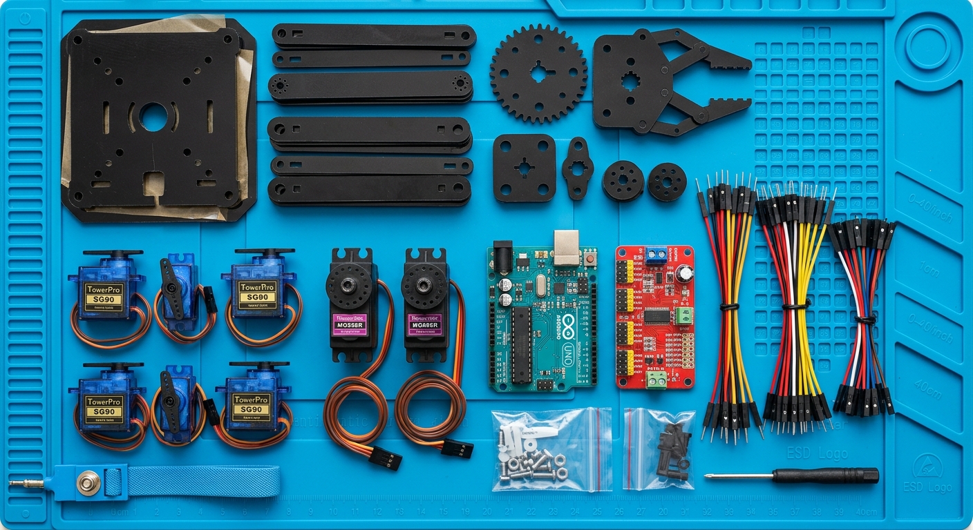
Hardware You’ll Need
Here are the parts you’ll need to build your own robotic arm:
- Arduino Uno R3
- Desktop Robotic Arm Kit (Acrylic)
- MG996R Servo Motors (for the base/shoulder)
- SG90 Micro Servos (for the wrist/gripper)
- PCA9685 16-Channel Servo Driver
- 5V 4A DC Power Supply (to power the servos via PCA9685)
- Jumper Wires
Writing the Code
To control the PCA9685, we highly recommend installing the Adafruit PWM Servo Driver Library through the Arduino IDE Library Manager.
Here is a simplified snippet to initialize the board and move a specific servo:
#include <Wire.h>
#include <Adafruit_PWMServoDriver.h>

// Called this way, it uses the default address 0x40
Adafruit_PWMServoDriver pwm = Adafruit_PWMServoDriver();

#define SERVOMIN  150 // This is the 'minimum' pulse length count (out of 4096)
#define SERVOMAX  600 // This is the 'maximum' pulse length count (out of 4096)
#define SERVO_FREQ 50 // Analog servos run at ~50 Hz updates

// Which servo on the driver board we are moving (0-15)
uint8_t servonum = 0;

void setup() {
  Serial.begin(9600);
  Serial.println("Robotic Arm Test!");

  pwm.begin();
  pwm.setOscillatorFrequency(27000000);
  pwm.setPWMFreq(SERVO_FREQ);
  delay(10);
}

void loop() {
  // Move servo to max position
  pwm.setPWM(servonum, 0, SERVOMAX);
  delay(1000);

  // Move servo to min position
  pwm.setPWM(servonum, 0, SERVOMIN);
  delay(1000);
}
In the full project, you will write custom functions to map angles (0-180 degrees) to the pulse lengths (SERVOMIN to SERVOMAX) so you can precisely command the arm to move to specific coordinates.
Grab your acrylic pieces, start assembling the frame, and let’s get those servos turning!