ElectronParade
Welcome back, builders! We’ve spent this entire module exploring the 555 timer, diving into everything from simple blinking LEDs to complex timing circuits. Now, it’s time to put all those pieces together into our Module 7 Capstone Project: the legendary Atari Punk Console (APC). This purely analog synthesizer is famous for its gritty, retro 8-bit sounds that perfectly mimic classic arcade games. It’s loud, it’s weird, and it is incredibly fun to play with.
How the Stepped Tone Generator Works
The Atari Punk Console is technically a “Stepped Tone Generator,” originally designed by Forrest M. Mims III. It relies on the interaction of two 555 timers (or a single 556 dual timer IC) to create its unique sonic footprint:
- The Astable Oscillator: The first 555 timer is wired in astable mode. This acts as the master clock, generating a continuous square wave. The frequency (pitch) of this wave is controlled by the first potentiometer.
- The Monostable Multivibrator: The output of the first timer feeds directly into the trigger pin of the second 555 timer, which is wired in monostable (one-shot) mode.
- The Magic Interaction: Every time the first timer pulses, it triggers the second timer. The second potentiometer controls the length of the pulse generated by the second timer. When you tweak both knobs simultaneously, the pulses interact and overlap, creating stepped, square-wave tones that sound straight out of a 1980s console.
Parts List
Here is what you will need to build your own Atari Punk Console:
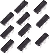
- 1x 556 Dual Timer IC (or two 555 Timer ICs)
- 2x 500kΩ Potentiometers (for pitch and pulse width control)
- 1x 1kΩ Resistor
- 1x 4.7kΩ Resistor
- 1x 0.01µF Ceramic Capacitor
- 1x 0.1µF Ceramic Capacitor
- 1x 10µF Electrolytic Capacitor
- 1x 8Ω Mini Speaker
- 1x 9V Battery and Battery Clip
- Breadboard and Jumper Wires
Wiring Overview
Building the APC requires a bit of patience, as there are quite a few jumper wires involved. Here is the general workflow:
- Power Delivery: Connect your 9V battery to the power rails of your breadboard. Ensure the ground and VCC pins of your 556 (or both 555s) are connected to the respective rails.
- The Astable Stage: Wire the first half of the circuit (the astable oscillator). Connect the first 500kΩ potentiometer and the 0.01µF capacitor to set the timing network.
- The Bridge: Connect the output pin of the first timer stage to the trigger pin of the second timer stage.
- The Monostable Stage: Wire the second 500kΩ potentiometer and the 0.1µF capacitor to the second timer to shape the pulse width.
- Audio Output: Route the final output pin through the 10µF coupling capacitor (to block DC voltage) and into your 8Ω speaker. Tie the other end of the speaker to ground.
Once you triple-check your wiring, plug in the 9V battery and start twisting those knobs! You have officially graduated from Module 7.
Hardware You’ll Need
To follow along with this lesson, you’ll need the following components: