ElectronParade
Welcome back to the Academy! Today we are taking a leap into one of the most versatile and ubiquitous components in modern electronics: the Operational Amplifier, or Op-Amp for short. If you’ve ever wanted to add a bit of “decision-making” logic to your analog circuits without writing a single line of code, you’re in the right place. Let’s dive right in!
What is an Op-Amp?
At its core, an Operational Amplifier is a high-gain electronic voltage amplifier with a differential input and, usually, a single-ended output. While they can perform a vast array of mathematical operations (hence the name “operational”), one of their simplest and most powerful applications is acting as a comparator.
The Op-Amp as a Comparator
A comparator does exactly what it sounds like: it compares two voltages. By feeding two different voltage signals into the Op-Amp’s inputs (the inverting - and non-inverting + inputs), the Op-Amp will output either its maximum or minimum voltage depending on which input is higher.
Here is why using an Op-Amp as a comparator is so incredibly useful:
- Hardware Logic: It allows your circuit to make a simple “yes/no” or “high/low” decision based purely on analog voltage levels.
- Sensor Thresholds: You can easily set a threshold voltage using a potentiometer. If a sensor’s output (like a light-dependent resistor or a temperature sensor) crosses that threshold, the Op-Amp triggers an action, like turning on an LED or a cooling fan.
- Signal Conditioning: It’s perfect for converting messy, fluctuating analog signals into clean, sharp digital square waves.
- Cost-Effective: Op-Amps are incredibly cheap and don’t require programming, saving you the hassle of adding a microcontroller to a simple project.
By understanding the comparator circuit, you unlock a whole new level of control in your hardware designs. In our next lesson, we’ll build our very first Op-Amp comparator circuit on a breadboard. Stay tuned!
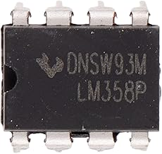
Hardware You’ll Need
To follow along with this lesson, you’ll need the following components: