ElectronParade
Lesson 147: Infinite Turns - Mastering the Rotary Encoder
In Lesson 116, we learned how to use a potentiometer to read rotational position. Potentiometers are great, but they have a physical limit—they hit a hard stop after about 270 degrees.
What if you want to navigate a long digital menu on an LCD screen, or turn a volume knob that spins endlessly in either direction? For that, you need a Rotary Encoder.
A rotary encoder looks like a potentiometer, but it spins forever and clicks as it turns.
How a Rotary Encoder Works
Instead of using internal resistance like a potentiometer, a rotary encoder works using tiny internal mechanical switches. As you turn the knob, it rapidly connects and disconnects two pins (labeled A and B) to ground.
By looking at which pin connects to ground first, the Arduino can determine not just that the knob is turning, but which direction it is turning. This is called quadrature encoding. Because it’s just clicking switches, the knob can spin 360 degrees infinitely!
Additionally, the common KY-040 module we will use today has a built-in push-button. If you press down on the shaft, it clicks!
Need the parts? Grab a pack of KY-040 Rotary Encoder Modules on Amazon. They are cheap, reliable, and come with the necessary pull-up resistors right on the board.
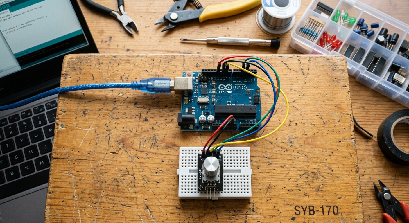
Wiring the KY-040
The KY-040 module typically has 5 pins. Since it relies on rapid digital switching, we don’t need the Analog pins. We will use standard Digital pins.
- Connect GND to Arduino GND.
- Connect + (or VCC) to Arduino 5V.
- Connect SW (Switch/Button) to Arduino Pin 4.
- Connect DT (Data / Pin B) to Arduino Pin 3.
- Connect CLK (Clock / Pin A) to Arduino Pin 2.
The Code
To read the encoder, we need to constantly monitor the CLK pin to see when its state changes, and then instantly check the DT pin to see if it’s HIGH or LOW (which tells us the direction).
// Define the pins
int clkPin = 2;
int dtPin = 3;
int swPin = 4;

int counter = 0;
int currentStateCLK;
int lastStateCLK;

void setup() {
  Serial.begin(9600);

  // Set pins as inputs
  pinMode(clkPin, INPUT);
  pinMode(dtPin, INPUT);

  // The button needs an internal pull-up resistor
  pinMode(swPin, INPUT_PULLUP);

  // Read the initial state of CLK
  lastStateCLK = digitalRead(clkPin);
}

void loop() {
  // Read the current state of CLK
  currentStateCLK = digitalRead(clkPin);

  // If the last state and current state are different, a pulse occurred
  if (currentStateCLK != lastStateCLK) {

    // If the DT state is different from the CLK state, we're turning clockwise
    if (digitalRead(dtPin) != currentStateCLK) {
      counter++;
    } else {
      // If they are the same, we're turning counter-clockwise
      counter--;
    }

    Serial.print("Position: ");
    Serial.println(counter);
  }

  // Update lastStateCLK with the current state for the next loop
  lastStateCLK = currentStateCLK;

  // Check the push button
  int btnState = digitalRead(swPin);

  // If we detect a LOW signal, the button is pressed
  if (btnState == LOW) {
    Serial.println("Button pressed!");
    delay(200); // Simple debounce to prevent multiple triggers
  }
}
Upload this code, open your Serial Monitor, and give the knob a twist. You’ll see the counter increase as you turn right, and decrease as you turn left. Press the knob down, and it will register a click!
Rotary encoders are the absolute best way to add a premium, professional “clicky” interface to your Arduino projects. Try combining it with the I2C LCD screen from Lesson 127 to build an interactive menu!