ElectronParade
Lesson 143: Arduino to Arduino - Wireless Communication with NRF24L01
In our previous lessons, we used Infrared and Bluetooth to communicate with an Arduino using a remote or a smartphone. But what if you want two Arduinos to talk directly to each other? Whether you’re building a weather station that sends data to a base unit, or a remote-controlled car with a custom joystick controller, Arduino-to-Arduino communication is a superpower.
Enter the NRF24L01+. This small, low-cost radio transceiver is a favorite in the maker community. It uses the 2.4GHz band (like Wi-Fi) to send and receive data packets over impressive distances.
 The NRF24L01 module is small but powerful, allowing two microcontrollers to form a local network.
Recommended Hardware
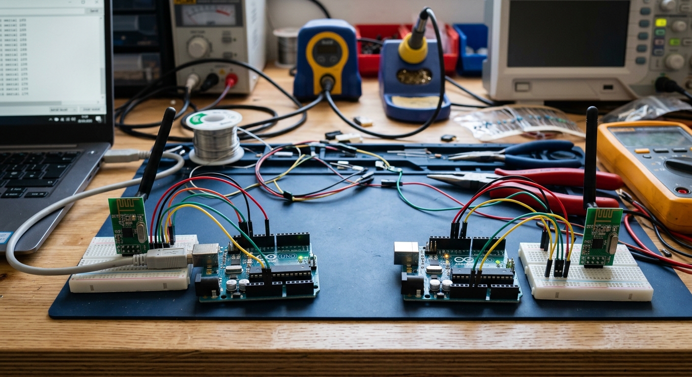
For this lesson, you will need two sets of hardware (a transmitter setup and a receiver setup).
- 2x Arduino Uno R3: ELEGOO UNO Project Super Starter Kit (Contains one Arduino and a breadboard. You will need a second Arduino board).
- 2x NRF24L01+ Transceiver Modules: NRF24L01+ 2.4GHz Wireless Transceiver Module
- Jumper Wires & Breadboards
Understanding the NRF24L01
The NRF24L01 is a transceiver, meaning it can both transmit (send) and receive (listen for) data. Unlike Bluetooth, which is designed to connect to your phone, NRF24L01 modules are designed to talk to other NRF24L01 modules using a protocol called SPI.
SPI Communication
SPI (Serial Peripheral Interface) requires several pins to operate:
- MOSI (Master Out Slave In) - Sends data to the module.
- MISO (Master In Slave Out) - Receives data from the module.
- SCK (Serial Clock) - Keeps the data synchronized.
- CSN and CE - Used to select the chip and enable the radio.
Wiring the Module
Warning: The NRF24L01 strictly requires 3.3V for power! Connecting its VCC pin to 5V will instantly fry the module.
However, its data pins are 5V tolerant, so you can connect them directly to your 5V Arduino Uno.
Wire both the Transmitter Arduino and Receiver Arduino identically:
- VCC: 3.3V on Arduino (NOT 5V!)
- GND: GND on Arduino
- CSN: Pin 8
- CE: Pin 7
- MOSI: Pin 11
- MISO: Pin 12
- SCK: Pin 13
Writing the Code
To make things easy, we will use the fantastic RF24 library created by TMRh20. Go to your Arduino IDE Library Manager and install RF24.
The Transmitter Code
This code sends a simple “Hello World” message every second.
#include <SPI.h>
#include <nRF24L01.h>
#include <RF24.h>

RF24 radio(7, 8); // CE, CSN
const byte address[6] = "00001"; // Communication pipe address

void setup() {
  radio.begin();
  radio.openWritingPipe(address);
  radio.setPALevel(RF24_PA_MIN); // Use minimum power for testing
  radio.stopListening();         // Set as transmitter
}

void loop() {
  const char text[] = "Hello from Transmitter!";
  radio.write(&text, sizeof(text));
  delay(1000);
}
The Receiver Code
Upload this code to your second Arduino. Open the Serial Monitor at 9600 baud.
#include <SPI.h>
#include <nRF24L01.h>
#include <RF24.h>

RF24 radio(7, 8); // CE, CSN
const byte address[6] = "00001"; // Must match the transmitter!

void setup() {
  Serial.begin(9600);
  radio.begin();
  radio.openReadingPipe(0, address);
  radio.setPALevel(RF24_PA_MIN);
  radio.startListening(); // Set as receiver
}

void loop() {
  if (radio.available()) {
    char text[32] = ""; // Create a buffer
    radio.read(&text, sizeof(text));
    Serial.println(text);
  }
}
Power Issues? Add a Capacitor
The NRF24L01 is notorious for drawing sudden spikes of power during transmission. The Arduino’s 3.3V pin is quite weak. If your modules are dropping connections or refusing to work, the solution is almost always to solder a small capacitor (like a 10uF electrolytic capacitor) directly across the VCC and GND pins of the NRF24L01 module.
In our next lesson, we’ll learn how to measure gravity and orientation to build a Digital Smart Level!