ElectronParade
Lesson 129: Spinning Up - Controlling DC Motors with the L298N Driver
In earlier lessons, we learned how to make things move using servo motors. Servos are fantastic for precise positioning, but what if you want to build a wheeled robot or a motorized fan? For continuous, free-spinning motion, you need a standard DC Motor.
However, there’s a catch: DC motors require far more current than an Arduino pin can safely provide. If you connect a DC motor directly to an Arduino digital pin, you risk burning out the microcontroller! To bridge the gap, we use a component called a Motor Driver. The L298N is one of the most popular and versatile motor drivers available.
 The L298N driver acts as a heavy-duty switch, taking small control signals from the Arduino and delivering high power to the motors.
What You’ll Need
- An Arduino board (like the ELEGOO UNO R3)
- An L298N Motor Drive Controller Board Module
- A DC Gear Motor TT Motor with Wheel
- Breadboard Jumper Wires
- A separate power supply (like a 4xAA battery pack) for the motors
How the L298N Works
The L298N uses a circuit called an “H-Bridge” to control both the speed and direction of up to two DC motors.
It has three main types of connections:
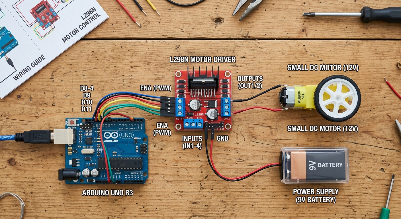
- Power In: You connect your battery pack (e.g., 6V-12V) to the 12V terminal, and the battery ground to the GND terminal. Always connect the Arduino’s GND to this same GND terminal to complete the circuit!
- Motor Out: The output terminals (OUT1 and OUT2 for Motor A, OUT3 and OUT4 for Motor B) connect to your DC motor’s wires.
- Logic In: These pins (IN1, IN2, ENA, etc.) connect to your Arduino. They tell the L298N which way to spin and how fast.
Wiring It Up
Let’s wire up a single motor (Motor A).
- Connect the Motor to
OUT1andOUT2. - Connect your Battery Pack Positive to the
12Vterminal on the L298N. - Connect your Battery Pack Negative to the
GNDterminal. - Connect the Arduino GND to the same
GNDterminal on the L298N. - Remove the little black jumper cap on the
ENApin (if present). - Connect
ENAto Arduino Pin 9 (for speed control via PWM). - Connect
IN1to Arduino Pin 8 (direction control 1). - Connect
IN2to Arduino Pin 7 (direction control 2).
The Code: Speed and Direction
To control direction, we set IN1 and IN2 to opposite states (one HIGH, one LOW). Reversing those states reverses the motor. To control speed, we use analogWrite() on the ENA pin, sending a value between 0 (stopped) and 255 (full speed).
// Define the L298N control pins
const int enA = 9;
const int in1 = 8;
const int in2 = 7;

void setup() {
  // Set all the motor control pins to outputs
  pinMode(enA, OUTPUT);
  pinMode(in1, OUTPUT);
  pinMode(in2, OUTPUT);

  // Start with the motor turned off
  digitalWrite(in1, LOW);
  digitalWrite(in2, LOW);
  analogWrite(enA, 0);
}

void loop() {
  // 1. Spin forward at full speed
  digitalWrite(in1, HIGH);
  digitalWrite(in2, LOW);
  analogWrite(enA, 255); // Full speed
  delay(2000); // Wait for 2 seconds

  // 2. Stop
  digitalWrite(in1, LOW);
  digitalWrite(in2, LOW);
  analogWrite(enA, 0);
  delay(1000);

  // 3. Spin backward at half speed
  digitalWrite(in1, LOW);
  digitalWrite(in2, HIGH);
  analogWrite(enA, 128); // Half speed
  delay(2000);

  // 4. Stop again
  digitalWrite(in1, LOW);
  digitalWrite(in2, LOW);
  analogWrite(enA, 0);
  delay(1000);
}
Upload the code and watch your motor come to life! In future lessons, we can connect a second motor and pair it with an ultrasonic sensor to build an autonomous robot car.