ElectronParade
Lesson 121: Seeing the Light - Introduction to Photoresistors (LDRs)
Welcome to Module 3! In our previous module, we relied on manual inputs like pushbuttons and potentiometers. Now, it’s time to make our Arduino smart enough to react to its environment automatically.
Our first sensor is one of the most common and easiest to use: the Photoresistor, also known as a Light Dependent Resistor (LDR).
 A photoresistor allows your Arduino to measure ambient light.
What is a Photoresistor?
A photoresistor is exactly what it sounds like: a resistor whose resistance changes depending on how much light hits its surface.
- In the dark: Its resistance is very high (often in the megaohms).
- In bright light: Its resistance drops significantly (down to a few hundred ohms).
By placing a photoresistor in a circuit, we can use an analog pin on our Arduino to “read” the light level.
The Voltage Divider
An Arduino cannot measure resistance directly; it can only measure voltage. To convert the changing resistance of the LDR into a changing voltage, we use a basic circuit called a Voltage Divider.
We need two resistors:
- Our variable Photoresistor.
- A fixed resistor (a 10k-ohm resistor works perfectly).
When they are connected in series between 5V and GND, the voltage at the point between them shifts depending on the light level. We connect this middle point to an Arduino analog pin.
Wiring It Up
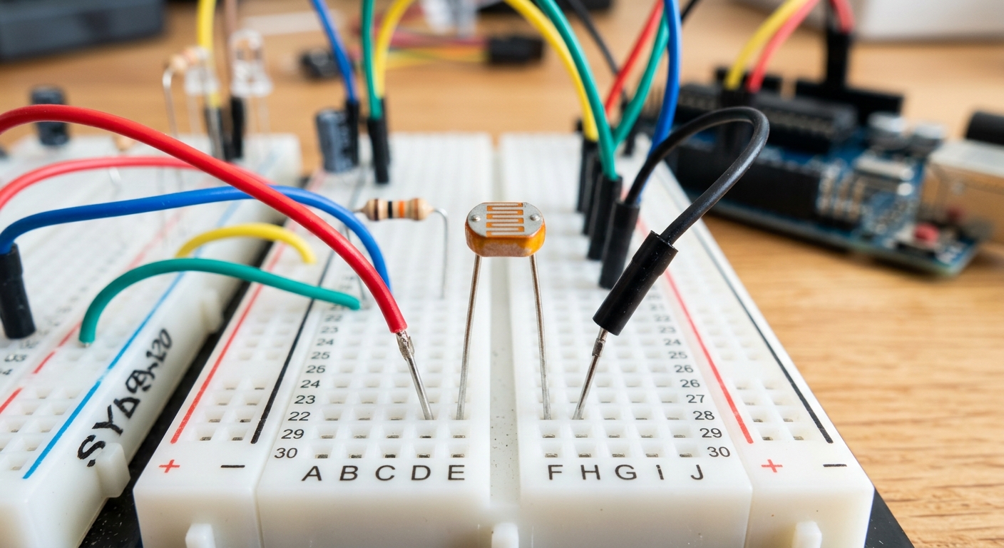
Let’s build a classic “Night Light” circuit that turns on an LED when the room gets dark.
- Connect the 5V and GND from the Arduino to your breadboard’s power rails.
- Place the Photoresistor on the breadboard.
- Connect one leg of the Photoresistor to 5V.
- Connect the other leg of the Photoresistor to a 10k-ohm resistor.
- Connect the other end of the 10k-ohm resistor to GND.
- Connect a jumper wire from the junction between the Photoresistor and the 10k resistor to Analog Pin A0.
- Add a standard LED to Pin 9 with a 220-ohm resistor to GND.
[Need to restock your components? Pick up a massive assortment of photoresistors and sensors here: photoresistors assortment]
The Code
We will read the analog voltage, print it to the Serial Monitor to see our baseline room light, and then turn on the LED if the value drops below a certain threshold.
const int ldrPin = A0;  // Photoresistor connected to A0
const int ledPin = 9;   // LED connected to Pin 9

int lightLevel = 0;     // Variable to store the sensor reading
int threshold = 400;    // The value at which it is considered "dark"

void setup() {
  pinMode(ledPin, OUTPUT);
  Serial.begin(9600);   // Start serial communication for debugging
}

void loop() {
  lightLevel = analogRead(ldrPin); // Read the light level (0-1023)

  Serial.print("Light Level: ");
  Serial.println(lightLevel);      // Print it to the monitor

  // If the light level is lower than our threshold, turn the LED on
  if (lightLevel < threshold) {
    digitalWrite(ledPin, HIGH);
  } else {
    digitalWrite(ledPin, LOW);
  }

  delay(100); // Short delay to prevent flickering
}
Calibrating Your Sensor
Upload the code and open your Serial Monitor (magnifying glass icon in the top right). Cover the photoresistor with your hand and watch the numbers drop. Shine your phone’s flashlight on it and watch them spike.
Depending on the lighting in your room, you might need to adjust the threshold variable in the code. If your room usually reads 600, and drops to 250 when you cover it, setting the threshold to 400 is perfect!
Up Next
Now that we can sense light, let’s learn how to sense temperature. In Lesson 122, we’ll introduce the TMP36 analog temperature sensor.