ElectronParade
Lesson 120: Capstone Project: The DIY Mood Light
Congratulations! You’ve made it to the end of Module 2. You now understand how to wire up basic components, write C++ code, read digital and analog inputs, and output PWM signals.
It’s time to bring all of those skills together in a single, polished project: A customizable RGB Mood Light.
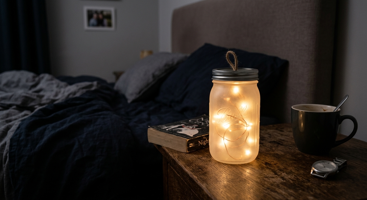 Our final project: A beautiful, customizable mood light.
The Project Concept
We are going to build a lamp that you can control manually.
- We will use an RGB LED as the light source.
- We will use three potentiometers to individually control the Red, Green, and Blue brightness, allowing you to manually mix any color.
- We will use the Serial Monitor to print out the current color values, so if you find a color you love, you can write down the recipe!
The Build
The Circuit
- The RGB LED: Wire up a Common Cathode RGB LED just like we did in Lesson 119. Connect Red to Pin 9, Green to Pin 10, and Blue to Pin 11 (each with a 220-ohm resistor). Connect the long leg to GND.
- The Knobs: Place three potentiometers on the breadboard.
- Connect the left leg of all three to 5V.
- Connect the right leg of all three to GND.
- Connect the middle wiper of Potentiometer 1 (Red) to Analog Pin A0.
- Connect the middle wiper of Potentiometer 2 (Green) to Analog Pin A1.
- Connect the middle wiper of Potentiometer 3 (Blue) to Analog Pin A2.
The Enclosure
An exposed LED is glaring to look at. To make it a true “mood light”, find a small frosted glass jar, a ping-pong ball with a hole cut in it, or fold a simple paper cube to place over the LED to diffuse the light.
The Code
We need to read the analog inputs (which give us 0-1023), mathematically scale those down to a PWM value (0-255), and apply that to the RGB pins.
// Define Pins
const int redLedPin = 9;
const int greenLedPin = 10;
const int blueLedPin = 11;

const int redPotPin = A0;
const int greenPotPin = A1;
const int bluePotPin = A2;

void setup() {
  pinMode(redLedPin, OUTPUT);
  pinMode(greenLedPin, OUTPUT);
  pinMode(blueLedPin, OUTPUT);

  Serial.begin(9600); // For debugging colors
}

void loop() {
  // 1. Read the potentiometers (0 - 1023)
  int redValue = analogRead(redPotPin);
  int greenValue = analogRead(greenPotPin);
  int blueValue = analogRead(bluePotPin);

  // 2. Map the 10-bit analog read value to an 8-bit PWM value
  // The map() function takes: (value, fromLow, fromHigh, toLow, toHigh)
  int redPWM = map(redValue, 0, 1023, 0, 255);
  int greenPWM = map(greenValue, 0, 1023, 0, 255);
  int bluePWM = map(blueValue, 0, 1023, 0, 255);

  // 3. Write the PWM values to the LED pins
  analogWrite(redLedPin, redPWM);
  analogWrite(greenLedPin, greenPWM);
  analogWrite(blueLedPin, bluePWM);

  // 4. Print the current mix to the Serial Monitor
  Serial.print("R: ");
  Serial.print(redPWM);
  Serial.print("\tG: "); // \t prints a tab space
  Serial.print(greenPWM);
  Serial.print("\tB: ");
  Serial.println(bluePWM);

  delay(50); // Small delay for stability
}
The Magic of map()
The map() function is one of the most useful tools in Arduino. Because our analog knob reads up to 1023, but our PWM output only goes up to 255, we can’t just pass the analog read directly into analogWrite(). The map() function proportionally scales the number down perfectly.
Wrapping Up Module 2
Turn your knobs and watch the colors mix inside your diffuser! You’ve successfully built an interactive physical computing device.
In Module 3, we’re going to ditch the knobs and start using sensors to make our Arduino react to the environment around it automatically.
[Ready for Module 3? Make sure your toolkit is stocked with a comprehensive Arduino Sensor Kit.]