ElectronParade
Lesson 119: RGB LEDs (Mixing millions of colors with code)
A standard LED emits a single color. But modern displays, smart bulbs, and gaming keyboards use LEDs that can change to almost any color imaginable. They achieve this using RGB LEDs.
 An RGB LED can produce a vast spectrum of colors by mixing red, green, and blue light.
What is an RGB LED?
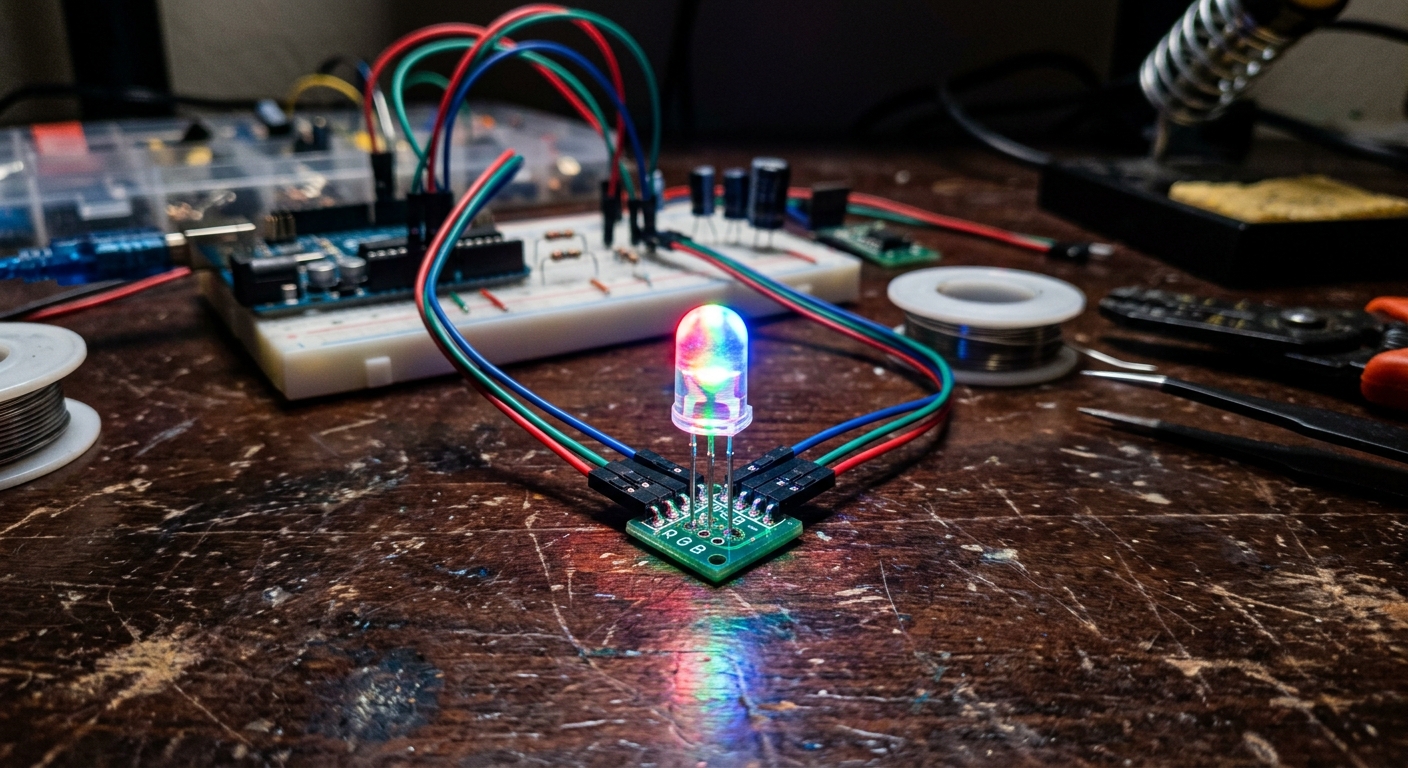
An RGB LED is actually three tiny LEDs packed into one plastic shell: one Red, one Green, and one Blue.
Because all the colors in the light spectrum can be created by mixing these three primary colors of light, we can trick the human eye into seeing purple, orange, or white just by adjusting the brightness of the individual red, green, and blue elements.
If you look closely at an RGB LED, you’ll see it has four legs.
- One leg for the Red anode
- One leg for the Green anode
- One leg for the Blue anode
- One long common leg.
Common Anode vs Common Cathode
There are two types of RGB LEDs:
- Common Cathode: The longest leg goes to Ground (GND). You apply positive voltage (HIGH) to the R, G, and B legs to turn them on. (This is the most intuitive type).
- Common Anode: The longest leg goes to 5V. You connect the R, G, and B legs to Ground (LOW) to turn them on.
For this lesson, we will assume you are using a Common Cathode RGB LED.
The Circuit
- Place the RGB LED on the breadboard.
- Connect the longest leg (Common Cathode) to GND.
- Connect the Red leg to Arduino Pin 9 through a 220-ohm resistor.
- Connect the Green leg to Arduino Pin 10 through a 220-ohm resistor.
- Connect the Blue leg to Arduino Pin 11 through a 220-ohm resistor.
Notice that pins 9, 10, and 11 are all PWM pins (they have the ~ symbol). This is vital!
Mixing Colors with PWM
If we just use digitalWrite() to turn the pins HIGH and LOW, we can only get 7 basic colors (Red, Green, Blue, Yellow, Cyan, Magenta, White).
To get smooth blends and millions of colors, we must use analogWrite() (PWM) to adjust the brightness of each channel from 0 to 255.
int redPin = 9;
int greenPin = 10;
int bluePin = 11;

void setup() {
  pinMode(redPin, OUTPUT);
  pinMode(greenPin, OUTPUT);
  pinMode(bluePin, OUTPUT);
}

// Create a custom function to make setting colors easy
void setColor(int redValue, int greenValue, int blueValue) {
  analogWrite(redPin, redValue);
  analogWrite(greenPin, greenValue);
  analogWrite(bluePin, blueValue);
}

void loop() {
  setColor(255, 0, 0);  // Pure Red
  delay(1000);

  setColor(0, 255, 0);  // Pure Green
  delay(1000);

  setColor(0, 0, 255);  // Pure Blue
  delay(1000);

  setColor(255, 255, 0); // Yellow (Red + Green)
  delay(1000);

  setColor(80, 0, 80);   // Dim Purple
  delay(1000);
}
By changing the values passed into the setColor() function, you can match almost any color hex code you find online!
[Don’t have an RGB LED? Get a pack of Clear RGB LEDs to experiment with color mixing.]
In the next lesson, we will combine this RGB LED with analog inputs to build our Module 2 capstone project.