ElectronParade
Lesson 110: Reading Schematics
In Lesson 108, we built a circuit using a breadboard. The instructions were written out step-by-step: “Connect the resistor to row 10, then plug the LED into the same row…”
While that works for a simple LED circuit, trying to describe a complex circuit with text is like trying to describe a painting over the phone. It’s confusing, error-prone, and incredibly slow.
That’s why engineers use Schematic Diagrams.
 A schematic diagram is a map of an electronic circuit.
The Universal Language
A schematic diagram is a map showing how electronic components connect to one another. Just like a geographical map uses symbols for roads, rivers, and cities instead of drawing realistic pictures of them, a schematic uses standard symbols for resistors, capacitors, and batteries.
Learning to read a schematic is learning the universal language of electronics. Once you understand the symbols, you can look at a circuit designed by someone on the other side of the world and understand exactly how to build it.
Key Concepts of Schematics
Before we look at the symbols, there are two crucial rules you must understand about reading schematics:
1. It’s About Connections, Not Physical Layout
This is the most common stumbling block for beginners. A schematic does NOT show you what the circuit looks like in real life.
A schematic might draw a resistor an inch away from an LED, connected by a long drawn line. But when you build it on your breadboard, you might plug them into the exact same row with no wire between them at all.
The schematic only cares about what connects to what, not where the components physically sit on your desk.
2. Lines are Wires
The solid lines connecting the symbols represent conductive paths (wires, or the copper traces on a circuit board). We assume these lines have zero resistance.
The Basic Symbols
Let’s meet the most common characters in our schematic alphabet:
Power Sources
Every circuit needs power.
- Battery: Represented by alternating long and short parallel lines. The long line is always the positive (+) terminal, and the short, thicker line is the negative (-) terminal.
- VCC / Power Rail: Often, to avoid drawing lines back to the battery all over the page, an upward-pointing arrow or a circle is used to indicate a connection to the positive power supply (labeled like
+5Vor+9V). - Ground (GND): Represented by a set of downward-pointing horizontal lines that get progressively shorter, forming a triangle shape. Any point in the schematic connected to a ground symbol is connected together back to the negative terminal of the power supply.
The Resistor
In the US and Japan, the resistor is drawn as a zig-zag line. (In Europe, it is often drawn as a simple rectangle). Usually, the resistance value (e.g., 10kΩ) will be written next to it.
The LED (Light Emitting Diode)
The symbol for a diode is a triangle pressing into a flat line, representing that current can only flow in one direction (the direction the triangle points). For an Light Emitting Diode, two small arrows are added pointing diagonally away from the symbol, representing light shining out.
The Capacitor
A basic capacitor is drawn as two parallel lines with a gap between them, mimicking the two parallel conductive plates inside the physical component.
If the capacitor is polarized (like an electrolytic capacitor, which must be plugged in a specific way), one of the lines will be curved, or a small + sign will be placed next to one plate.
Connecting the Lines
When two lines (wires) cross on a schematic, do they connect?
- Dot = Connection: If two lines cross and there is a solid dot (a “node”) at the intersection, those wires are electrically connected.
- No Dot = No Connection: If two lines cross and there is no dot, they are simply passing over each other without touching (like an overpass on a highway).
- (Note: In older schematics, a little “hump” or semi-circle was drawn when a wire jumped over another to show they didn’t connect, but modern standards usually just rely on the presence or absence of the dot).
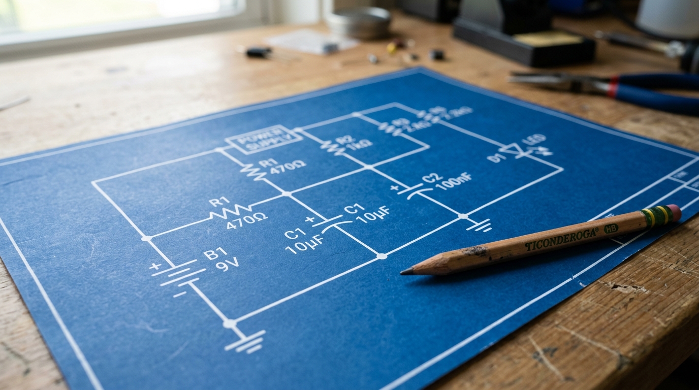
Putting It Together: The LED Circuit
Let’s revisit our simple breadboard circuit from Lesson 108, translated into a schematic:
- Start at the positive terminal of the Battery symbol.
- Follow the line to the Resistor symbol.
- Follow the line from the other side of the Resistor to the flat side (Anode) of the LED symbol.
- Follow the line from the point (Cathode) of the LED to the Ground symbol.
- (The negative terminal of the battery is also connected to Ground, completing the loop).
It’s that simple!
[Looking to build more complex schematics? Check out this excellent Assorted Component Kit to ensure you have the parts on hand when you read a new diagram.]
Practice Makes Perfect
The best way to learn schematics is to practice. Take a look at the open-source hardware projects online. Don’t worry if you don’t recognize every symbol yet—focus on tracing the paths and seeing how the basic building blocks fit together. Soon, you’ll be reading circuits like a pro!